Hi Neil, you probably remember me from the YouTube comment section, I was the one saying that you needed to drive the motors in constant current mode. I have thought a lot about your project over time and I’ve come to this conclusion. Is you want to make life easy you would just use 1 big motor for the electric car conversion, but putting that idea aside. If you want you can use a speed driven system but I would not do this because: it’s very hard to get all motors to spin the same speed (even with an ODrive) and also in the beginning when you’re gaining speed, what is your vel setpoint going to be? So I would say you just use ODrive’s to drive your motors in constant current witch is the same as constant torque because: it doesn’t matter what speed the car is going in the beginning when ramping up, the torque will be applied and you will gain speed at the highest possible rate and also you don’t have to worry about motor speeds that need to be the same, because they will automatically ajust when needed. Just think about it this way: when you’re sending no current, there’s no torque so no acceleration, when you go full trottle, you’re sending max amps to the motors, so you’re gaining speed as fast as possible until you’ve come to the maximum velocity or you trottle down.
If you have any questions, please ask them, I want your project to work out!
I do remember and appreciate your comments thank you.
I like to hear others thoughts as it may spark something I hadn’t thought of or spark an idea for someone else to try
I will most likely set up closed-loop control using
some sort of PID map that changed the P I and D values as the demand, load and RPM changed to get the maximum efficiency out of load sharing motors (kind of like a throttle map of an ICE car). I agree that it would be easier to put one motor in, although that would not offer the same degree of challenge, plus I think it looks cool
Unfortunately, I can’t use the ODrive to drive the MGF product just yet as I will be running at 200A per channel. Unless there is one in the pipeline to run at this current continuously ;-). And don’t worry I am a seasoned electronics engineer that has been in the electronics industry since 1994 working on numerous systems that include closed-loop control (back when we used boolean logic and karnaugh mapping to reduce logic gates) yes I’m that old, I used to teach valve theory for 4 years too . I am still learning too, especially with new emerging technology and from clever people such as Oskar who created the ODrive
The ODrive will be used to drive the axis of my milling machine to create the parts for the MGF project.
Maybe you could test drive the MGF when complete see what you think
just an update, I hope you don’t mind the continuous updates.
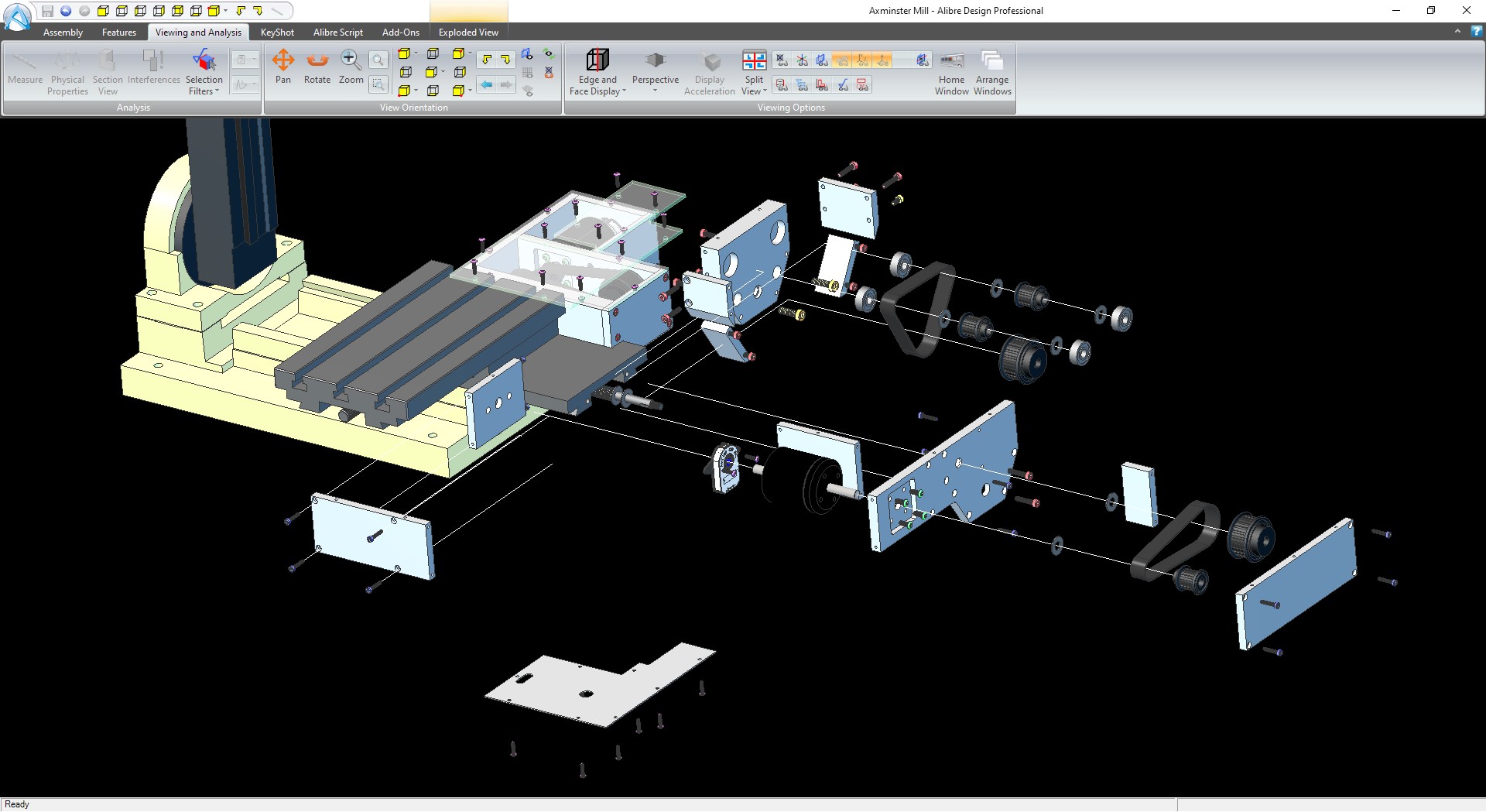
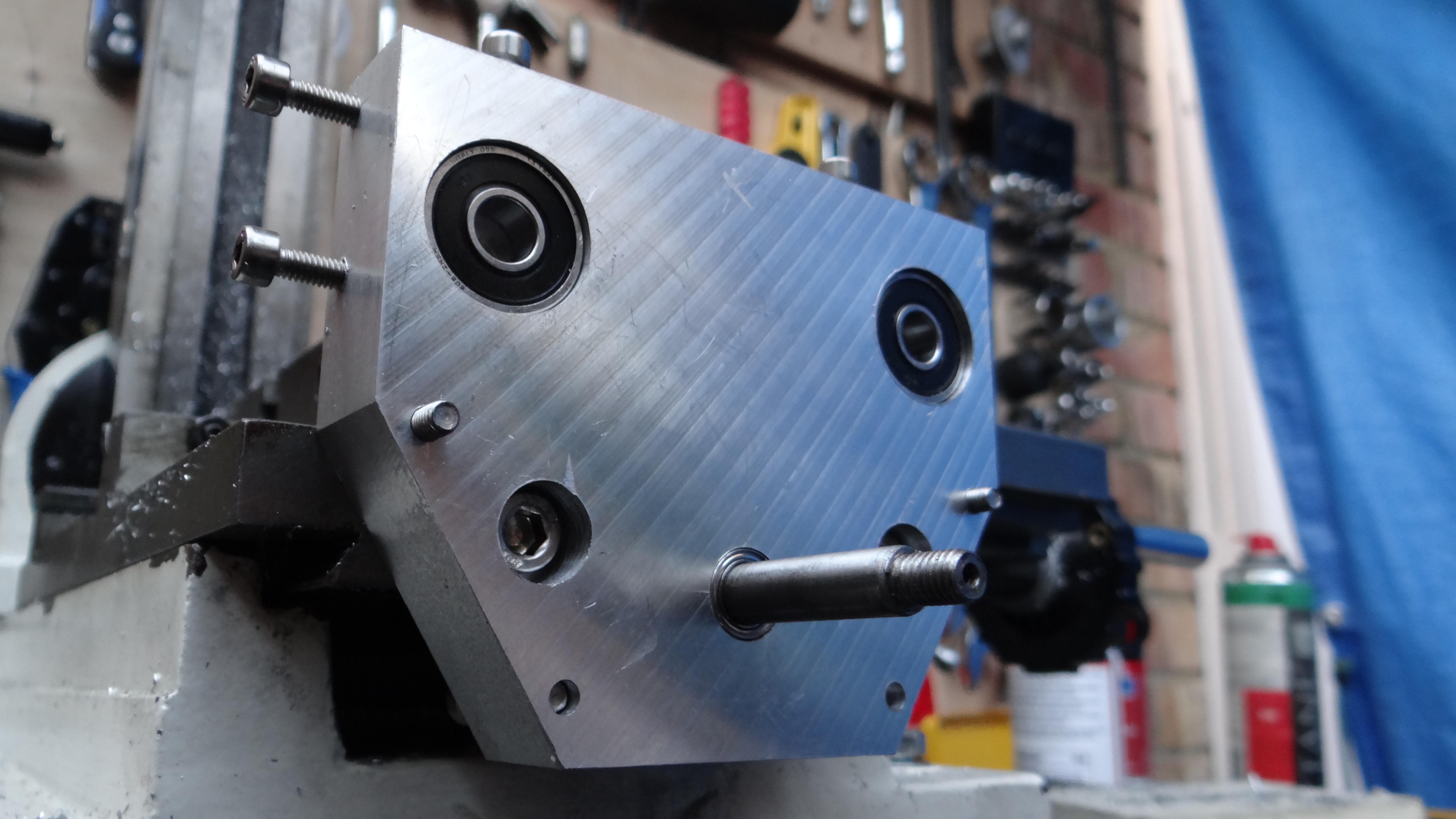
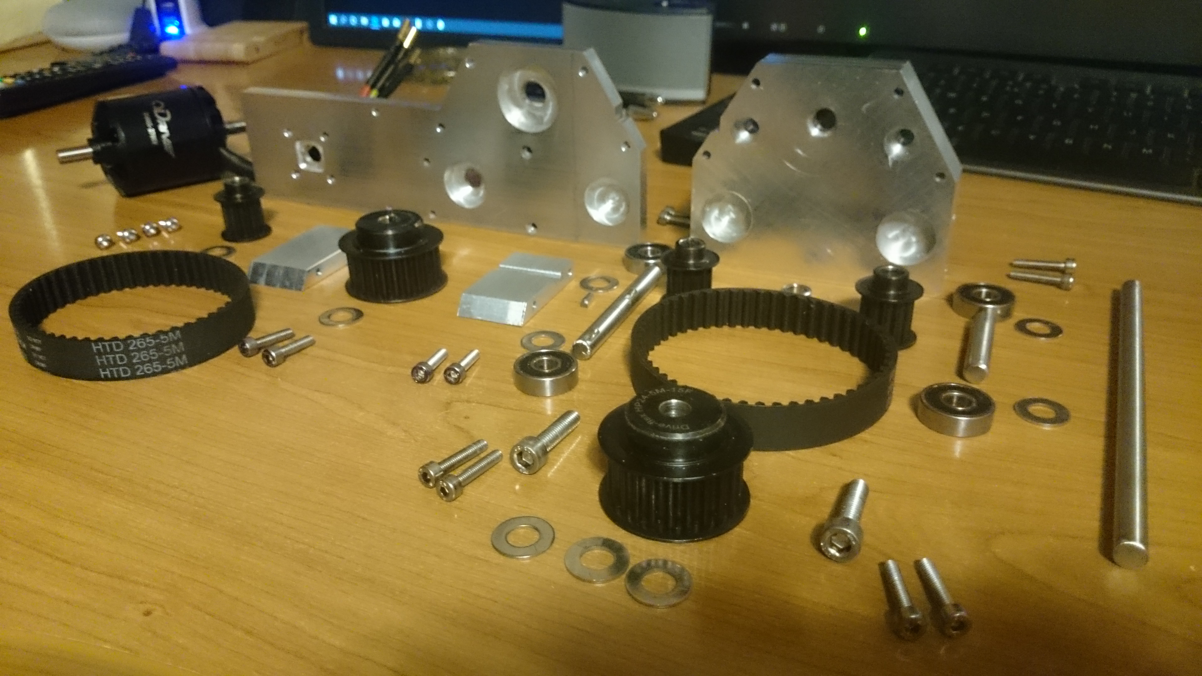
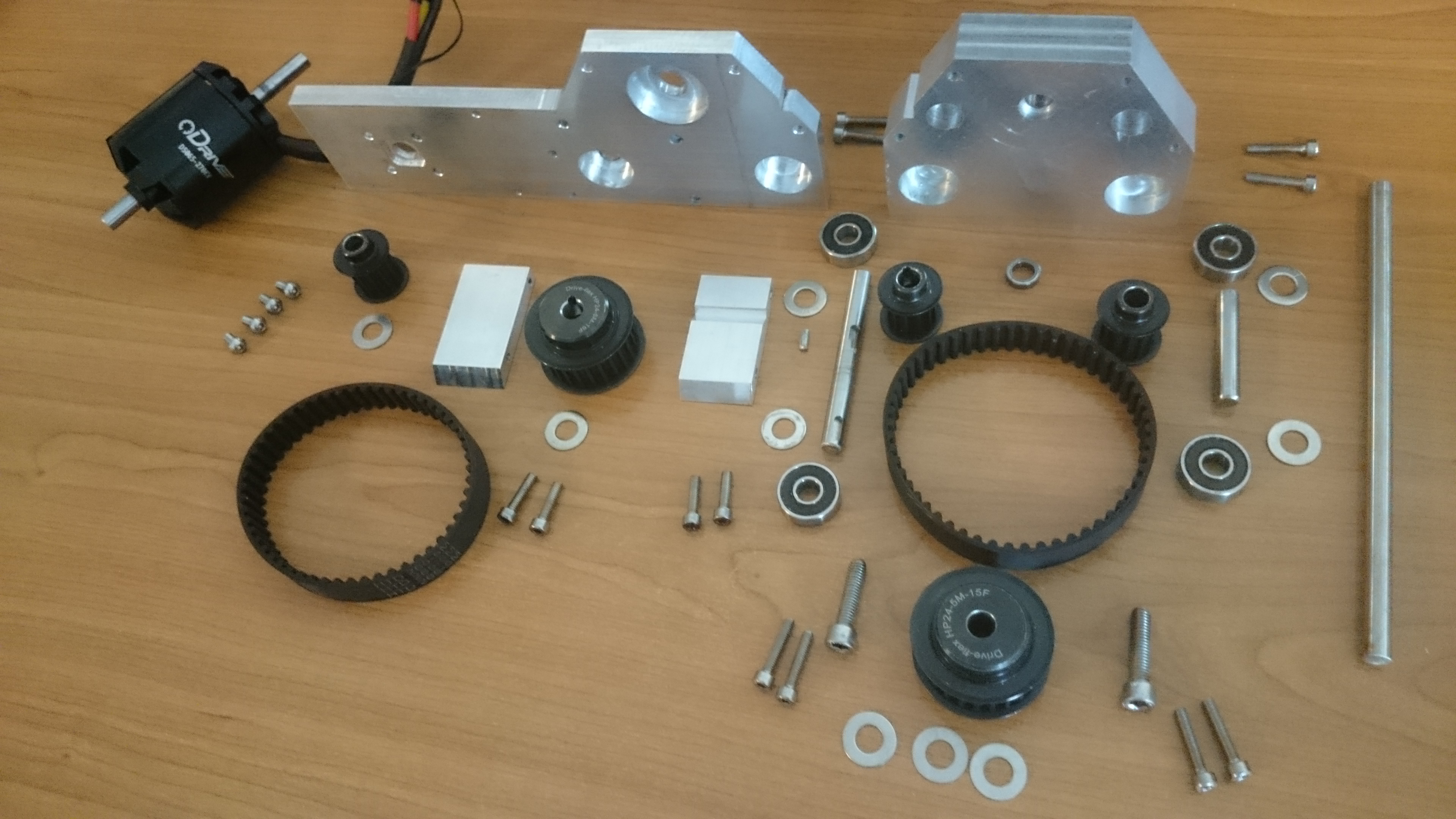
I have re-re and re-designed the whole X & Y drive units to be slimmer and allow maximum table travel, where I am now ordering the rest of the parts, re-assembling the mill then manually machining the designed parts.
I will probably do the Y axis first to test and set up the system off-load, then use the Y-axis initially to help machine the X-axis (kind of like a 1 axis CNC (sounds like a useless product)), I shall be filming every step too, plus the ODrive setup if that helps anyone.
Here is the finished CAD picture (it may change during testing).
What made you chose the 2 stage reduction would it have been easier to just have an extra small pulley on the motor does that add extra unnecessary backlash and inacuracy to the system also have you considered using very low kv motors and ditch the gear reduction alltogether
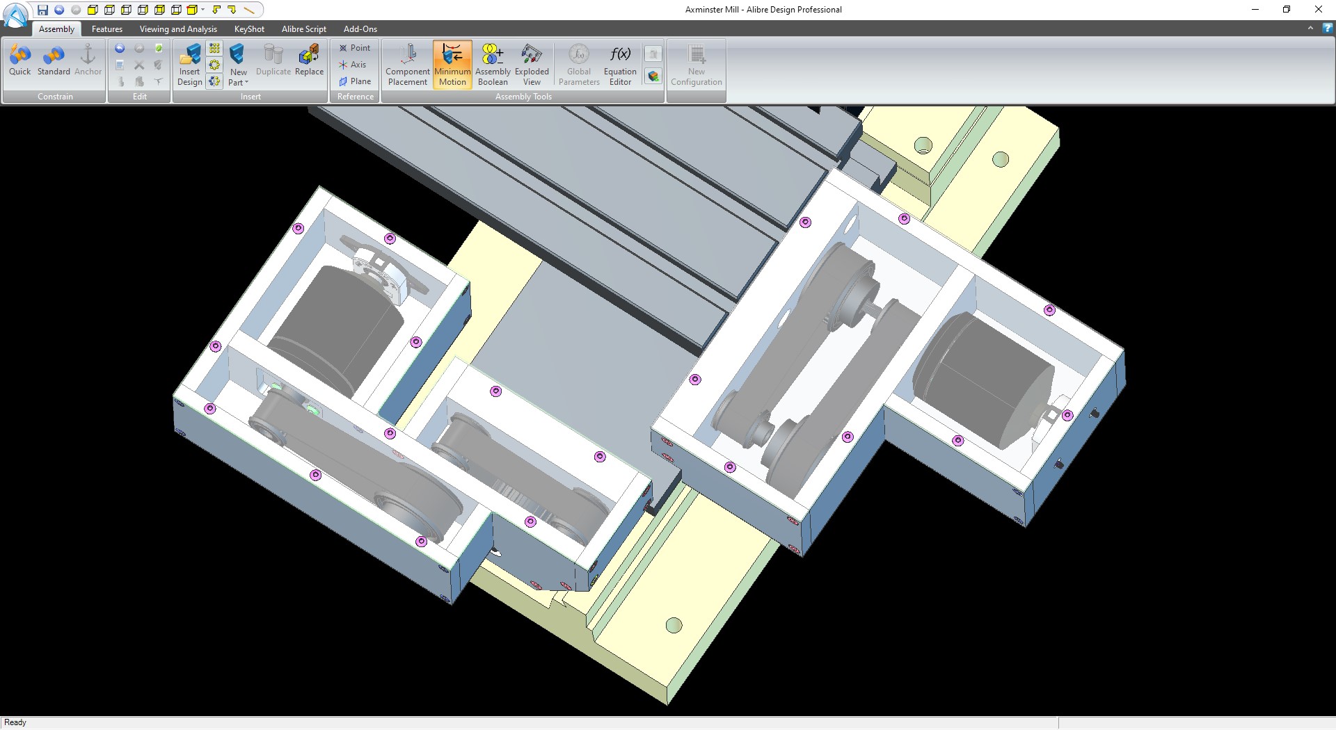
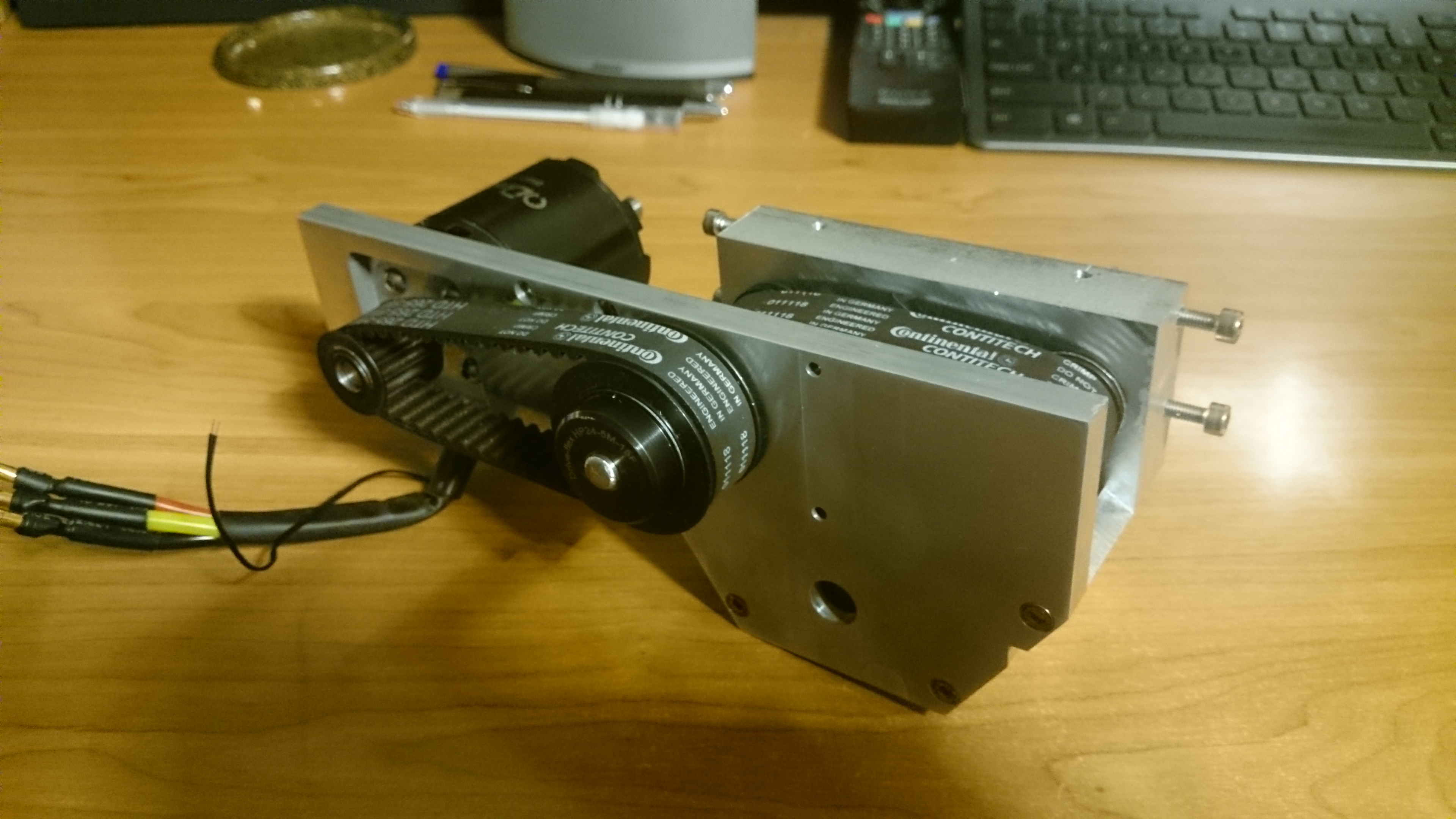
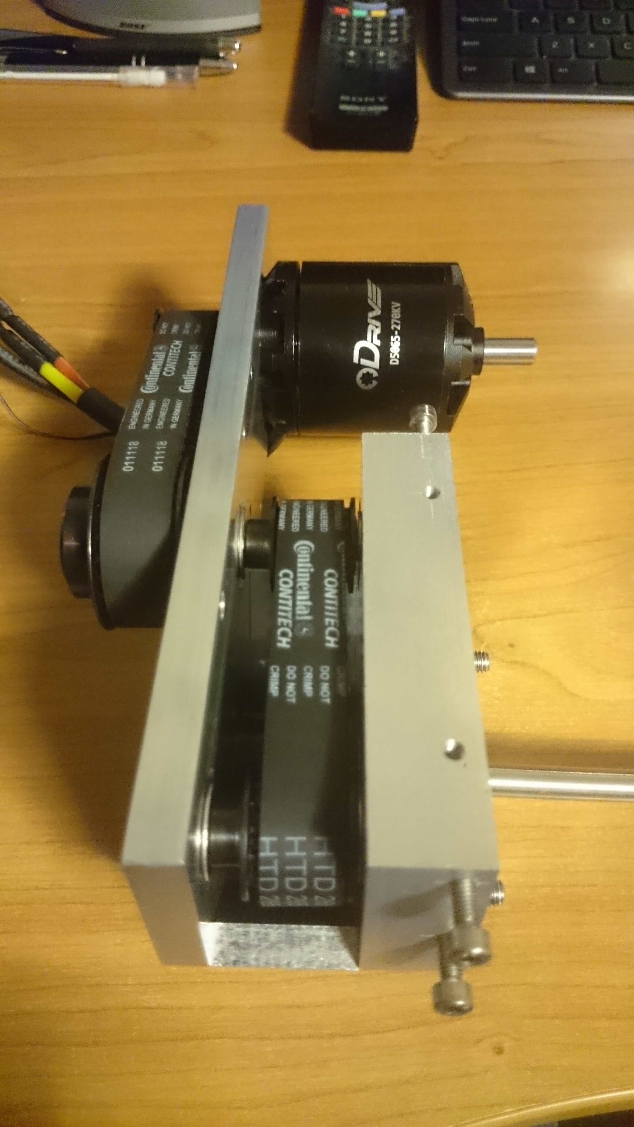
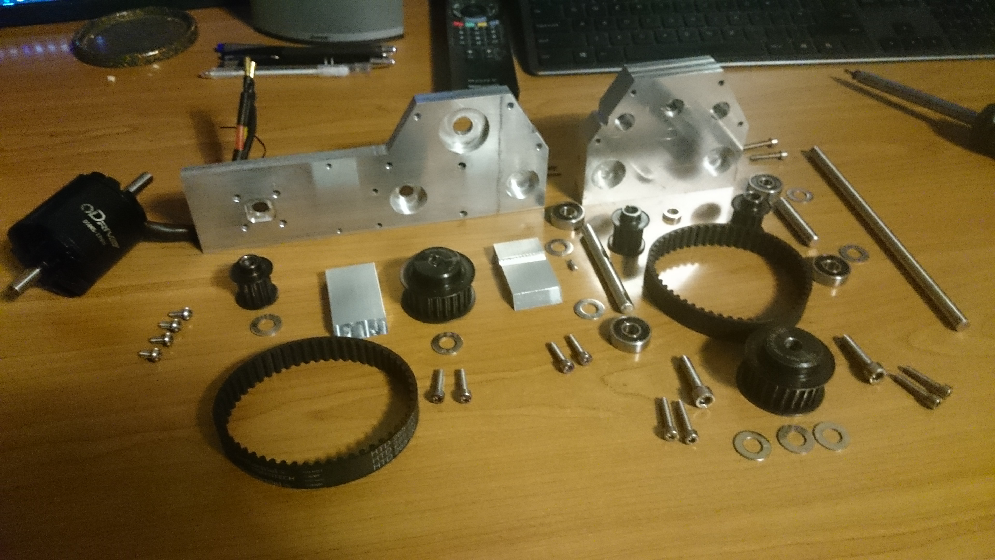
My initial thought was for the easy placement of the motor, where I didn’t want it sticking out the front too much as it has to squeeze through a doorway when taking it out and putting it away. So the front motor sits neatly to the side, plus the belt drive allowed for a reduction with hardly any backlash (with the heavy-duty HTD belts). Also, I wanted to use the ODrive with the motors it was tested with as it needs to be reliable (or fun to tweek).
With the backlash, this should be easily removed in programming/Mach 3, I think it’s impractical to chase down and try to fix all backlash, although as you said you wouldn’t want to introduce more
The motors produce around 2Nm at full current draw, so this would give somewhere below 8Nm at the leadscrew (taking into account friction) although probably wouldn’t need to run it at that. To eliminate chatter and the mill table drifting while cutting, I will play around with the X & Y axis locks and how much torque goes through the leadscrew to drive them.
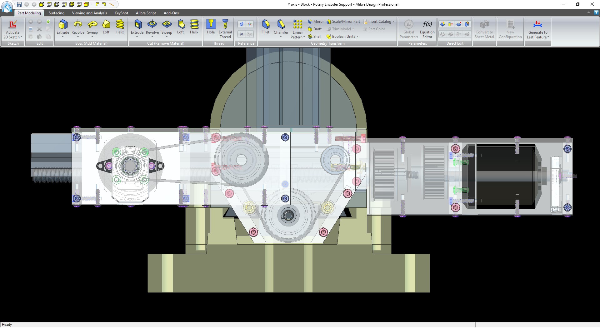
Here is Part 2 of the milling conversion, where I am currently editing Part 3.
I am well on the way to testing the first ODrive, just doing some more milling tonight so that I can fit the rotary encoder, then test off the machine.
I’ll be adding a tensioner idler pulley to each belt to take the slack away too.
It takes me a while due only being able to do this in the evenings and a couple of hours at the weekend. Would love to do this full time
Wow, just wow, these ODrive systems are fantastic, so stable and accurate.
I am putting together a video of first install and setup of the system, where my first attempt shows my own shortfalls not reading the help and then stepping through the fine setup. Hopefully, this will help others setup their ODrive’s.
Please let me know if I’m just covering old ground or if this will actually help anyone.
Here is a couple of pictures from the video files I’m using.
This is a cool project! Excited to see how it turns out.
Quick note, as Wetmelon mentioned, you can use absolute encoders to avoid any movement on startup. You calibrate once, after that no rotation when starting up! It works well, I’m using that myself.
Thanks, what encoders are you using? I may look into them and put them directly on the milling table as well as the motors. With the startup sequence, I would get 0.5mm of movement on the table (minus backlash) so absolute would work better.
My machine is getting noisy too, the motor brushes on the 240v 150W motor are suffering after 10 years, so I may just order another ODrive, 1800W BLDC and some belts to do a little upgrade.
Heads up though, the latest ODrive comes with the latest firmware from master branch, not RazorsEdge. If you want those features you’ll have to specifically build and flash RazorsEdge. Since you have the latest ODrive you can follow the procedure here to flash.
I don’t know of any precompiled releases of RazorsEdge, but you can follow this guide to build it yourself.
At the moment I will test with the AMT-102’s as I’ve already machined the mounts for that and see how they fare, then try the AS5047P’s for a bit of comparison. Ideally with any Mill you don’t want any movement on startup
The video is taking a while to edit as I am using 2 cameras and capturing the screen too.
Wow @Dev255, this is a cool project. I’m curious as to what you’re planning to use for a CNC firmware. Are you planning on using one of the more traditional options and using the step/direction interface or are you planning to do something different?
Thank you @robopilot99, I’m looking at a few options, possibly Step/Direction initially from Arduino G-code or something similar, plus a direct control mode to tap in co-ordinates and choose a hole to cut (so kind of like manual control’ish). This will help with quick projects that need a quick feature cutting out so I don’t have to 3D CAD every time.
The control part is a little up in the air at the moment as the plan usually changes by the time I get to that point
I have now successfully set up and tested the ODrive and BLDC motor
I decided to make a video covering the whole journey for a new/novice/noob ODrive user. Where I had never set up one of these or used python, so this video will hopefully give those that are unsure of trying this system more confidence to just give it a go.
All of the set up was done by following the “Getting Started” guide on the ODrive website, so hats off to all who wrote that
This video steps through: -
Installation of the Anaconda Software
Installation and configuration of the Zadig software to communicate with the ODrive
Stepping through the Getting Started guide while carrying out the setup
Actually reading the Getting Started guide (I forgot to put it back into Loop Control Mode, doh!)
Tweaking the tuning to get more out of the BLDC
Here is the video (CNC Part 4 - ODrive Set up): -
I hope this helps
Also I can’t remember sharing Part 3, so here is that one also: -
I am currently editing my Mill conversion Part 5 video and thought I’d put a little update on here.
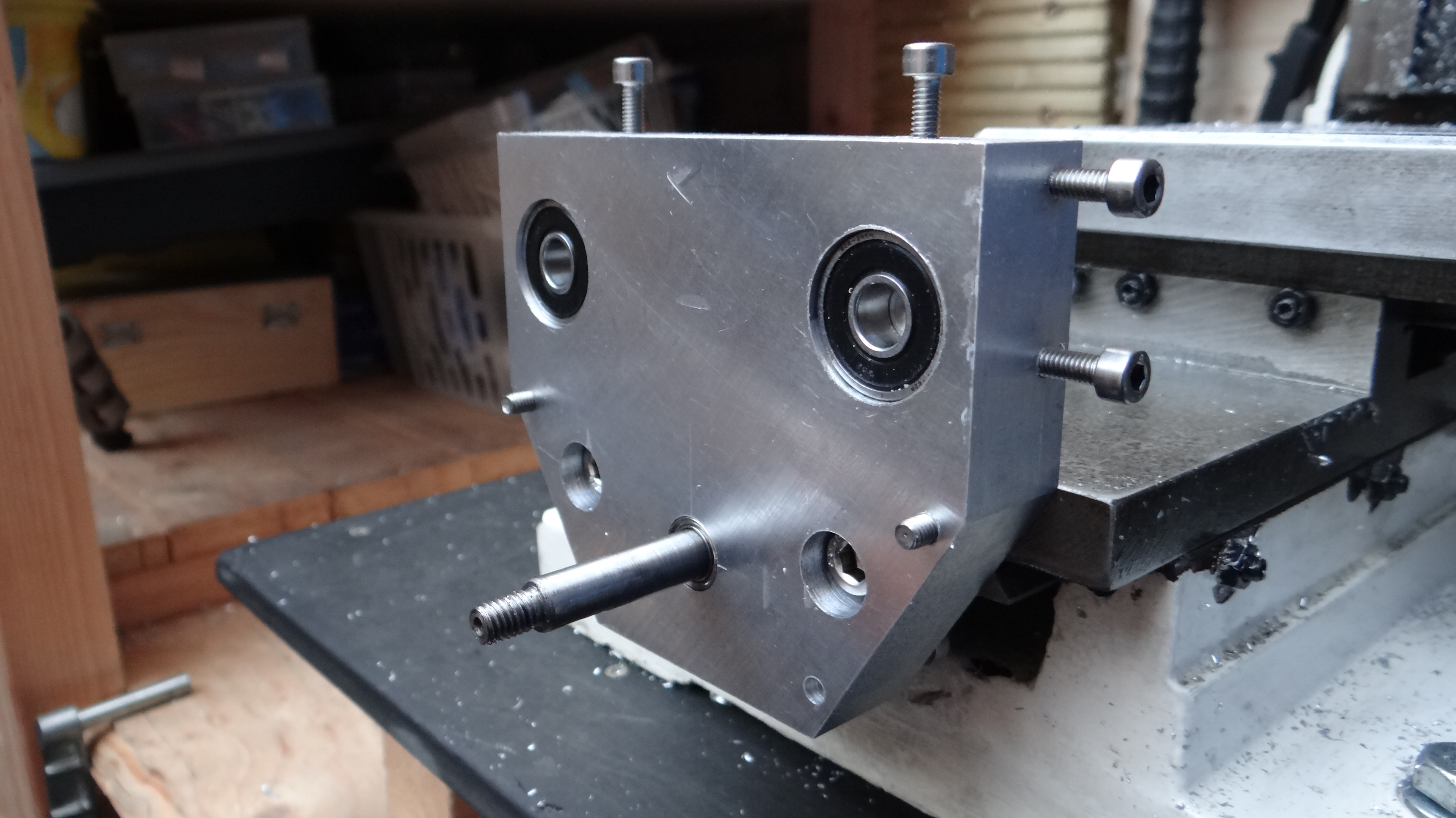
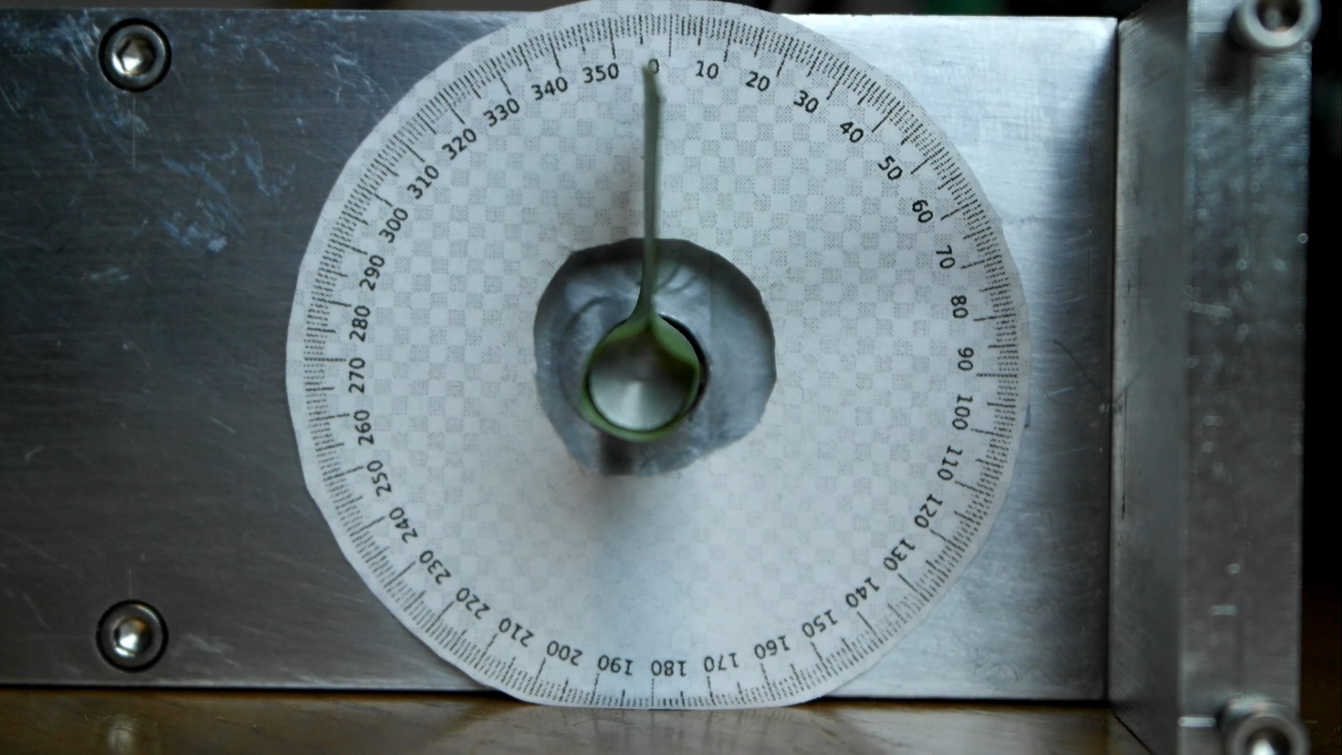
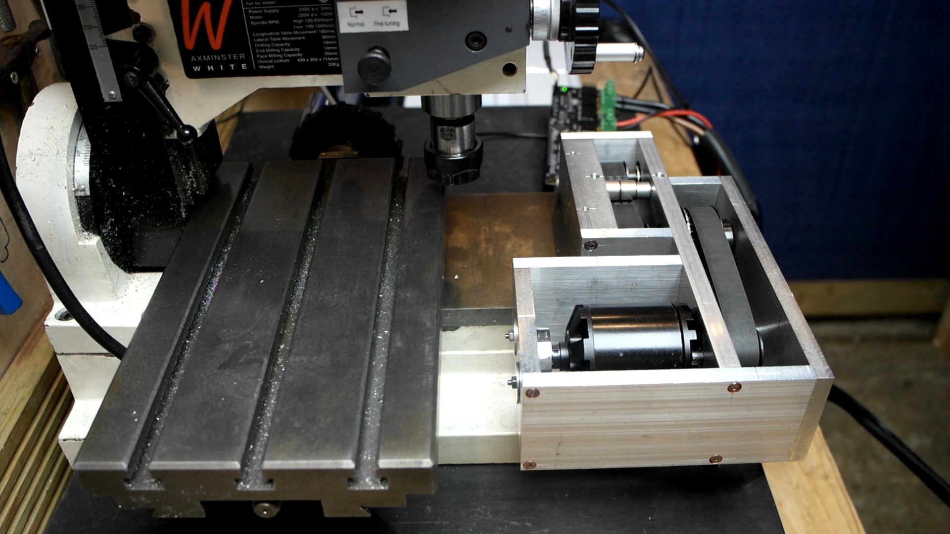
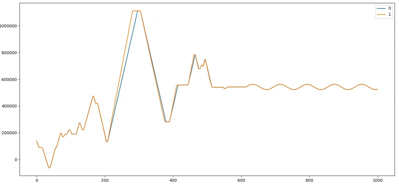
Wow, again these ODrives are cool and very accurate. I have the Y-Axis up and running on batteries that re continuously charged by a 50W solar panel (not at night obviously ;-). The D5065 Motor runs well with the AMT102 encoder now I have the system re-tuned on batteries, where I can achieve a velocity limit of 350k
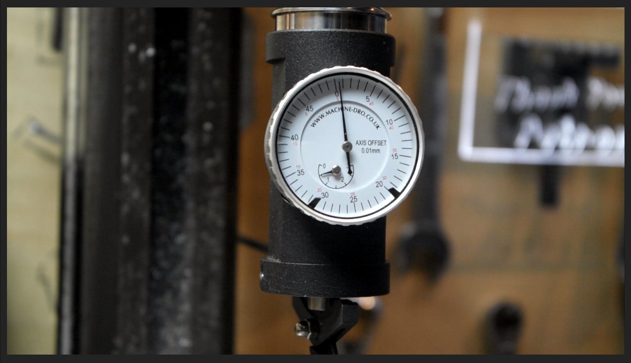
I have very little backlash on the whole drive system and can accurately repeat table movement shown using a co-axial dial indicator (ignoring the 0.01mm per graticule, I can’t accurately test the distance with this).
I think the system will have to be tweaked more, although very happy with the current performance.
The next step is to connect an Arduino, write a sketch and machine out the X-Axis items.
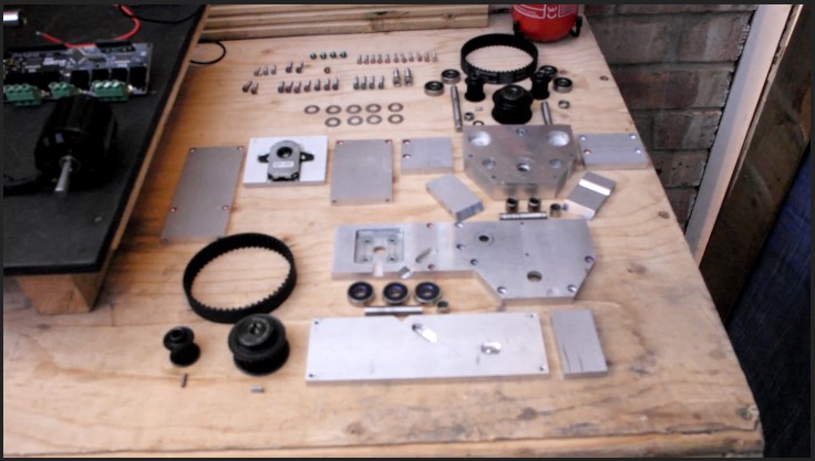
Will keep you posted. Here are some current pictures so far: -
I have just made Part 5 pubic on YouTube, so here it is: -
Feel free to comment, I’m learning a lot about G-Code and Arduino control at the moment and will be looking to control the ODrive via the ASCII commands as I feel this gives a good level of control for CNC and getting feedback from the ODrive.
From the tests in the video, I will be using the Arduino to control end stops, backlash compensation and G-Code control, so the ODrive has a nice time just looking after the precision motor control.
I have tested the whole table crashing into the back at various speeds with the motor current set to 20A (more than adequate with 4:1 drive reduction) with no damage to anything or belts slipping, where the ODrive just jumps out of Closed Loop Control as expected. Very happy with that .
I hope you are enjoying this project, please let me know what you think, even if you spot something wrong that I am doing (I’m learning too).
Well, I have the milling machine working on the Y-Axis with a Joypad pinched from a faulty indoor toy helicopter (re-using a redundant item is always best in my book).
The Joypad connects to an Arduino Mega2560 which directly sets up and controls the ODrive.
An LCD and LED 8x8 Matrix is also connected to the Arduino to see all the necessary control and status information from the Arduino Sketch (program).
I have been away for a good few days recently, although took everything with me apart from the Milling Machine. Hence why there is an 8x8 LED matrix connected, this replaced the milling machine to show each mm moved by the Y-Axis in order to tune all the values in the program.
So, what videos am I currently working on?
Connecting up the components to the Arduino.
Explaining through the Sketch (Arduino program).
Tuning the ODrive, Testing its accuracy and milling out an Airsoft part using the Joypad control. (Very accurate by the way
As you can see there has been a lot of work carried out in the background and now with most of the program written it will be easy to set up the X and Z-Axis when connected. Just the G-Code element to write for the CAD to CNC function, this will allow for parts designed on CAD to be automatically machined out.
I hope you are enjoying this project, all this will greatly speed up the MGF Electric Vehicle Conversion, where I will be able to machine out 3 parts at a time and much faster than I can manually machine them :-D.
Please feel free to comment on anything.
Kind Regards,
Neil.
P.S. I can’t seem to upload pictures at the moment (popup with “undefined method `original_sha1=’ for #”), so here are the links to them: -
Have you had any problems with noise on the encoder lines? I’m working on a similar project with linux CNC and I think noise on the encoder lines is causing the odrive to pick up the index pulse wrong during startup. I haven’t tried adding filter capacitors yet tho. Nice Work!
 or spark an idea for someone else to try
 . I am still learning too, especially with new emerging technology and from clever people such as Oskar who created the ODrive
 see what you think