Turning a Mill into CNC to help with an electric car conversion

Hi Noodles, sorry, I just spotted your post, I’ve been so busy with the project and working my day job.

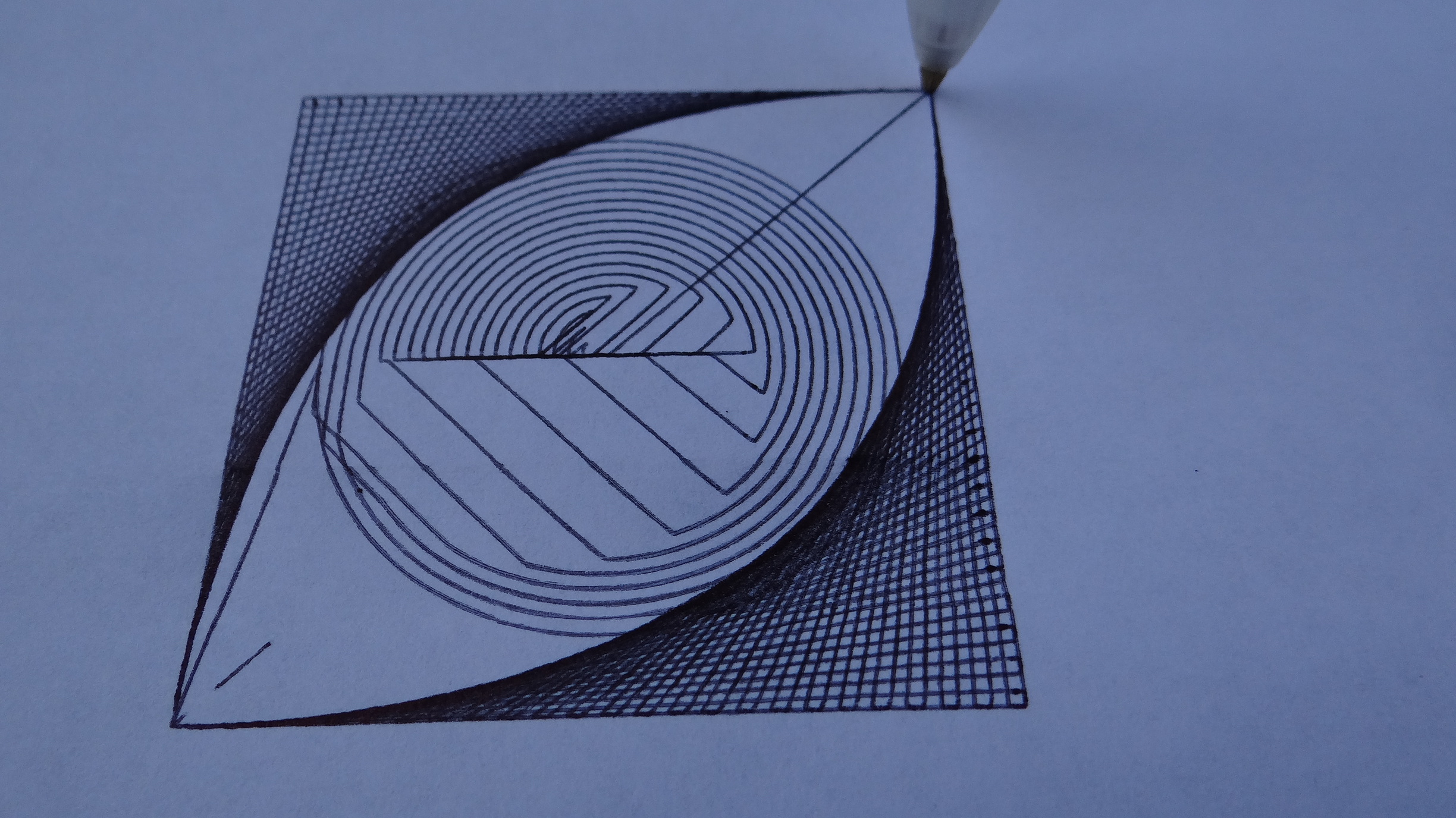
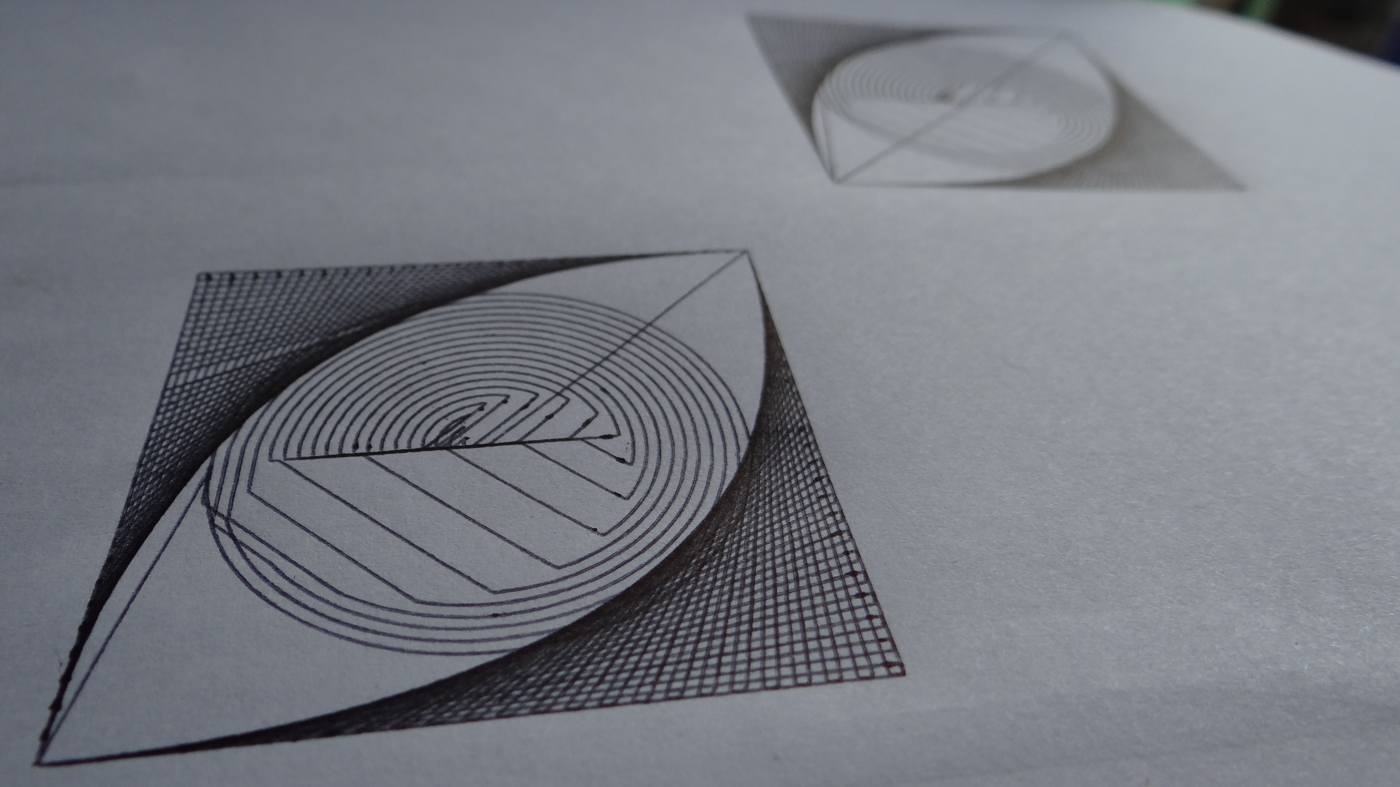
Thank you, it’s coming along nicely.

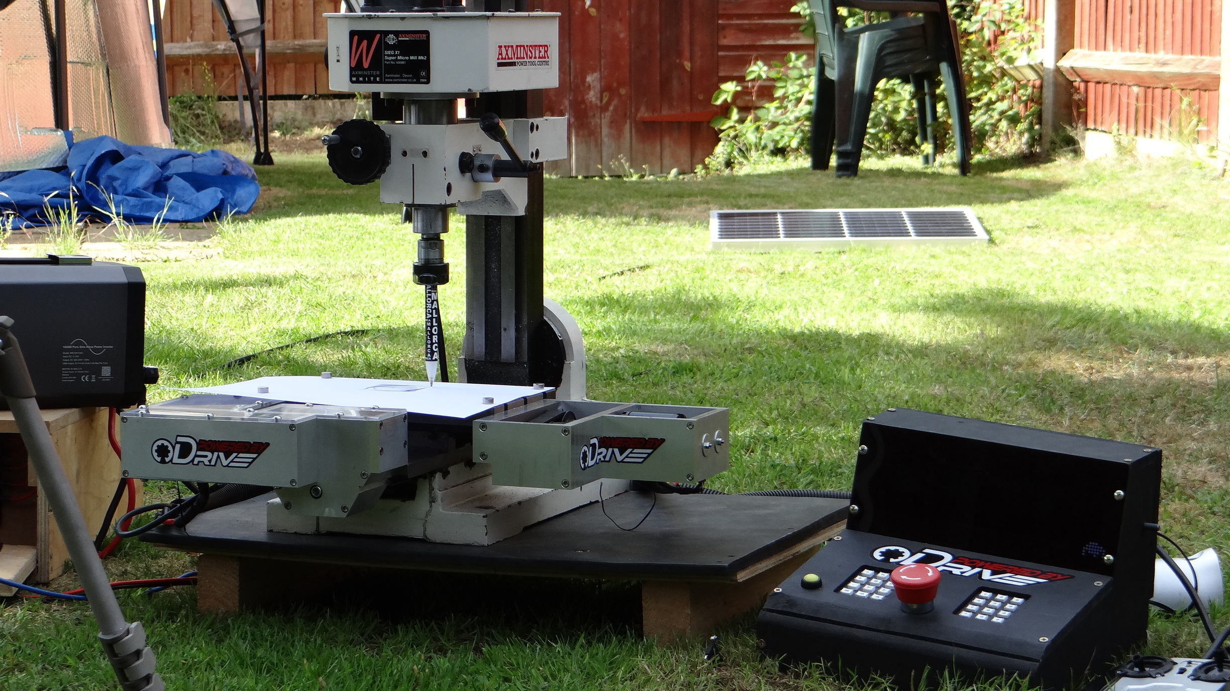
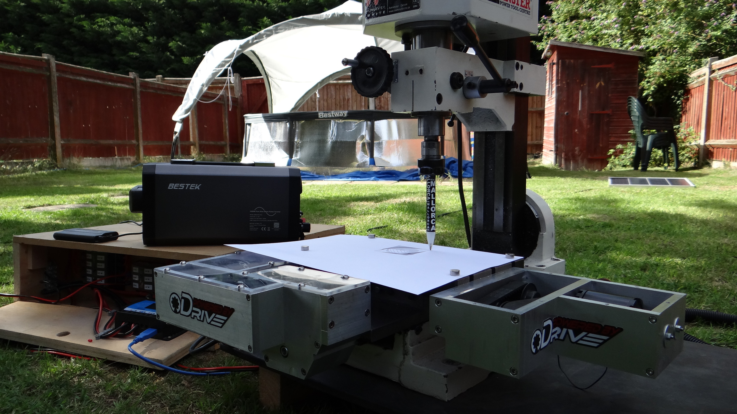
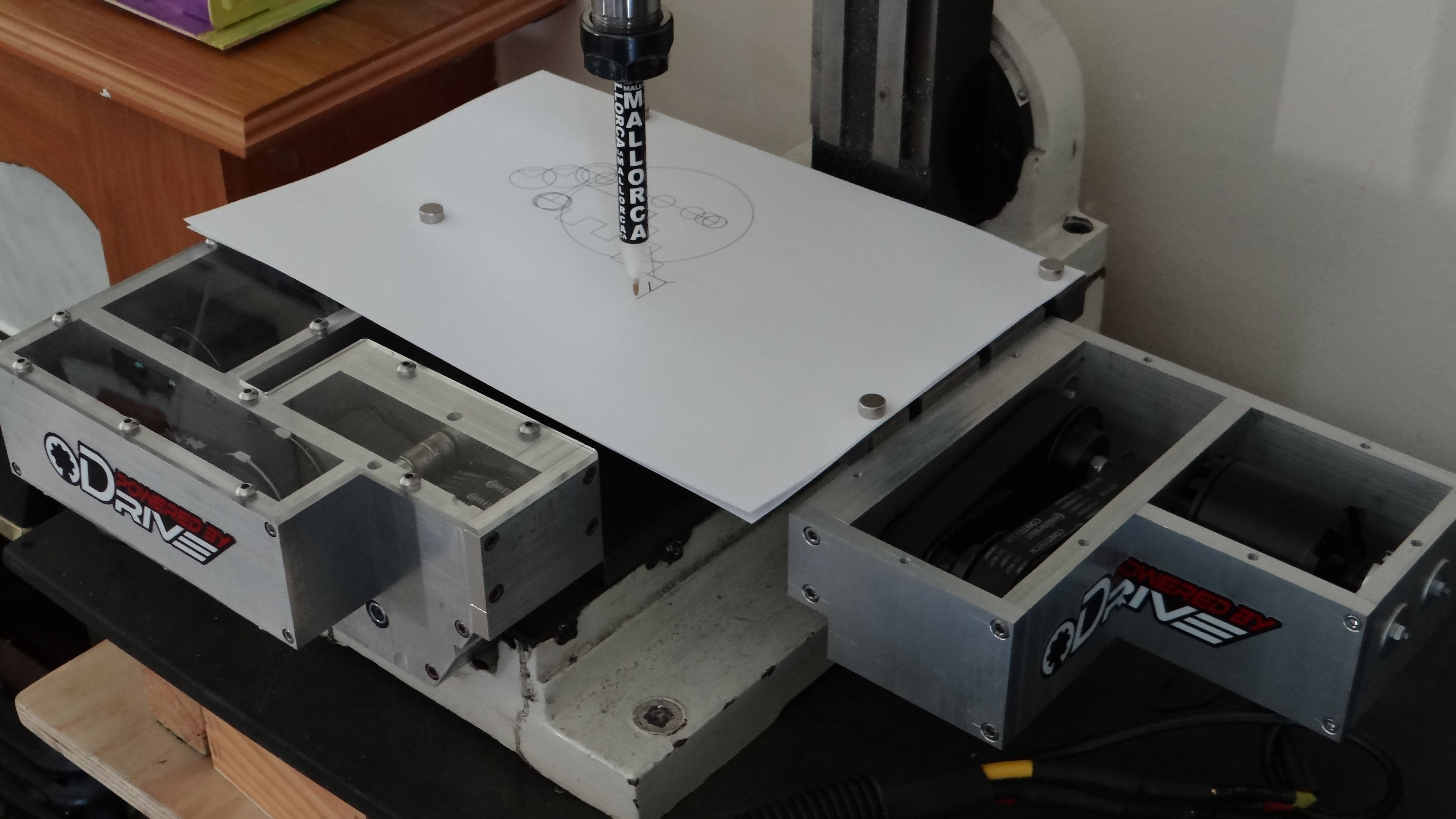
I haven’t had any issues with noise at all, everything works very well even with the standard lead that comes with the encoder running next to the motor lines for 50cm and with the motor current set to 60A. This is running on 12v lead-acid batteries; I believe most people have issues with power supplies, where ripple noise could come from that or don’t have a very solid mount for the AMT102. Even when I knock my drive unit fairly hard, there is no movement from the motor.

You could try adding a large capacitor close to the ODrive power input, or better still have a lead-acid battery connected as a reservoir then the PSU output would be smoothed out and just keeps the battery topped up. I would recommend a cheap wheelchair battery and set the PSU to 12.8v (float charge).

I hope that helps

2 Likes

Hmm good point. I would have never thought of the power supply. I am testing with a REALLY cheap power supply that is 100% not suitable for the final build and never thought to look at that. Thanks so much for pointing this out.

1 Like

No worries a cheap power supply would still be fine to top-up a reservoir battery. Hope you get it sorted.

Hi fellow ODrivers,

As suggested above, here is the video connecting up the Joypad and showing the sketch for this.

I will be showing the full sketch, although it needs a few more tweaks first, I have sorted out backlash too, where the Arduino sketch tests the commanded position for direction changes, then takes over and adds or takes away the backlash amount.

I’m working on the video showing that part at the moment, although in the mean time, here is the video showing the Joypad Sketch and circuit behind connecting it all up.

Enjoy,

Neil.

Part 6 - CNC Mill Conversion

1 Like

Hi all,

Just a little update on this one,

I have been successfully milling on a Joypad Controlled 1 Axis CNC machine, with the ODrive taking ASCII commands from an Arduino Mega 2560.

Not in this video, but I have now removed backlash by monitoring direction changes in the Arduino Sketch and rapidly moving the motor to take up the backlash with excellent results. My Y-Axis has a measured backlash of 0.12mm.

Also, I have now soldered the motor connections directly to the ODrive and (touch wood) had no errors ever since (twas my overtightening of the screw terminals that let me down, MY FAULT).

I say again… AMAZING CONTROLLER!

Here is Part 7 of my mill conversion…

CNC Mill Conversion Part 7

1 Like

Part 8 - The Arduino Sketch, Keypad function, ODrive control and Backlash Compensation.

Here is my latest video of the CNC Mill Conversion, this shows through the Arduino program and various functions to help in the understanding, I know 99% of people on here know this anywhooo, although thought I would share it with you to show you where I am at.

My Mill is now all stickered up ready for the next set of videos, Thank You Oskar for these.

Also, I have received the last two ODrive motors for this project and an ODrive v3.6 56v, so will be getting on with the Z Axis and spindle drive.

I hope you are all well in this crazy time, it has slowed me down with the build, although I am getting back up to speed now.

Stay Safe.

Kind Regards,

Neil.

My Channel - Dev255

1 Like

Hi all,

Here are some pics of the X-Axis parts I am currently working on. It’s a lot quicker when the machine does some of the work :smiley:

1 Like

A Small Mill Crash - Not too bad

I have almost completed the X-Axis and will be concentrating on the Z-Axis and spindle next. Is anyone interested in the code so far? If so, here it is: -

CNC Arduino Sketch Ver 1.7.1

I have been very busy with all sorts of projects and am now thinking of using the ODrive as the main motor controllers in the MGF Electric Vehicle project, although I would need 12 units initially, we shall see.

I have now reached 1000 subscribers and clocked well over 7000 hours of public watch time too, so thank you for anyone that watches and subscribed to my channel, hopefully, I will soon be accepted into the YouTube Partnership Program, where I will be able to fund more ODrive purchasing ;-D.

Happy ODriving,

Neil.

1 Like

Hello, I have an update ;-D,


When you are trying to get a milling machine to draw a line in any direction and through zero, you would think it was an easy (ish) operation, it’s just a line right?

That’s what I thought, although, you need lots of coffee, 3 solid nights of work, a rotated laptop and to write the program in excel to see all the figures…

Who would of thought a line was so complicated :sleeping:

Plus Excel really helps you see all the numbers and calculations in action without breaking the machine :smiley: Does anyone else use Excel?

So the X-Axis is complete apart from the perspex cover and working very well, where I have been testing it with pen and paper running straight lines at 90º and circles at different points and sizes; this to tune in the backlash amount for both Axes.

I have almost completely re-written the program on the controller to be much more efficient so everything runs smoothly, this has taken some time :yawning_face:

As the pics show, this is going very well, although taking a while to program, the next Axis (Z) will be much quicker to make as I have a mostly working CNC machine :-D.

Phew, this is a lot of work and I didn’t realise initially how complicated it would all get, although I am dedicated to making all this and my other projects work well and share as much as possible.

I know I haven’t been able to get as much out as I wan’t to, although have been continuously working on it.

Feel free to ask any questions.

Thank you,

Kind regards,

Neil.

Now to test the machine… and make a video…

OOOhhh, and thank you to all those that watch my videos on YouTube, I am now in the YouTube Partnership Program :star_struck:

2 Likes

Hi Neil, firstly; impressive and I’m lost for a better description, secondly when you mentioned the X plane did you mean Y as well?

Jerry

Hi Jerry, yes Y also sorry, where I had mostly programmed for the X when doing the Y-Axis, so I only have the Z-Axis and spindle motor to do, these will be controlled by a 56v ODrive V3.6 where the spindle motor will have a rotary encoder (AMT102) attached also, although will only use the full 8192 CPR for position control when tapping (if this works), where I hope to rotate the spindle at a defined speed and CW/CCW interpolated with the Z-Axis, so I can machine tap precisely (this will have to be tuned to each tap turns/mm etc) with a bit of luck ;-D.

Thank you for your kind words, it makes the project full worth the effort when appreciated :smile:

The machine is now completely running on Solar Energy too, I will share a picture of what it is currently doing…

You may want to not do the spindle as a brushless motor. Those are usually induction motors with dedicated controllers, where you can choose the rpm. Since you usually only change speeds when you change bits, or switch from steel to something else, periodically setting the spindle speed is usually sufficient.

However I can see how it would be useful to have an encoder on the spindle to detect rpm drop due to an excessive feed rate.

For those who’ve not run a metal mill, bits are consumables. How fast they get consumed, depends on how hot they run. If they run cool, then the cutter is harder, and lasts longer, or stays sharp longer. If the bit gets too hot, then it it will melt it’s self to your work piece, and cause a big mess. To make it stay cool, you control the cutting speed, which varies based on several factors, including, cooling liquid, material being cut, carbide or steel bit, and the radius of the bit, ie a 2 inch bit will run 4x as fast as a 1/2 inch bit at a given rpm, and the feed rate.

There are two of the primary reasons to use induction motors.

  1. is that at or near max rpm, and no load, power usage is very low, so for intermittent use, cooling is not an issue. Brushless motors warm up the magnets near max rpm.
  2. there are no permanent magnets near high speed components. On a mill, you will have steel dust/shards, you don’t want build up to attempt to stop a 5hp motor running at 400,000 rpm.

Milling machine motors are often sealed for reason 2, but they still need to vent the heat, so they use lots of surface area, and are large. Another option would to use liquid cooling, though that brings it’s own challenges. hobbyking has a 5kw water cooled boat motor though that may have a max rpm of 20k.

btw tesla uses induction motors, giving 2 reasons:
reduced parasitic drag (and longer battery life, ie more range) at highway speed.
not having to source more magnets than the world supply using rare earth materials (and not having to pay for the new supply of rare earth magnets).

-Michael

Hi Michael,

Hmm food for thought, the X and Y will be fully enclosed, so not affected by swarf and can be sealed if I chose to use coolant later on, although that could be stretching this machine to its limit. The motor will only be running at around 4000 RPM (2000 at spindle) most of the time as there is no real need to get full capacity out of the cutters, I don’t believe the spindle bearings would cope with double the axial load, so will probably just monitor the built in thermistor (all motors are ODrive D5065-270KV) and reduce the spindle and Axes speeds at the same rate if the temperature crosses an upper threshold (PID control again ;-). That’s a good point with using the rotary encoder to monitor load, that would be very accurate if calculated correctly, I could split the output of the AMT102 and monitor externally for fast action instead of bothering the ODrive when it’s busy. I need a small loop for quick load change reaction. I think these motors will be fine for heat on my setup as I am only running everything at around 12.8v which limits the max velocity from the ODrive. Plus, I already have the motors now :grinning:.

The main reasons for using the encoder on the spindle motor is to carry out controlled machine tapping without the need for expensive torque auto-reverse drive units, as these add even more cost, reduce accuracy as further from the spindle and use up some valuable Z-Axis height, so are fairly limiting on a home hobby mill.

What do you think so far though? I am impressed by everything ODrive :smiley: :+1:

You should look at my MGF EV project, I am going to have 24 x 3kW water cooled motors on there, anything more than 3kW and the speed controllers tend to get expensive. Here: https://youtu.be/QP8K7zrCqK4

Thank you,

Neil.

The machine in its natural habitat…

And running off Solar Energy…

Shhhhh, don’t disturb it.

I was testing speeds, line control, arc length, accuracy (ish with a pen), etc.

I had to modify the pen, putting the springs from other puns in to push the nib onto the paper, not retract it.

The machine is very accurate, where if you see a wobbly line in the picture, its only from the paper pushing down in the T-Slots.

Nice job! Where’s the video of it drawing that picture?

Aha, I was wondering how you got your bed so flat! :stuck_out_tongue:
I have an Axminster SX2 myself - but I’m not good enough with mechanics to CNC it.
How’s the backlash? Did you swap out the leadscrews for ballscrews?

That EV engine is just an abomination though. You aren’t actually going to build that are you?

1 Like

Hi towen,

Yes I will be building it, it’s a challenge and I wan’t to prove that multiple motors can work together and efficiently. The main point of making something like that is to show either how and why it all works or how and why it doesn’t. I won’t know till I try. I’m sure many projects get called abominations before they are fully working ;-D, how do we know unless we try :smiley: :+1:

I will upload a video within the next week or so, have to ensure my Patrons get first dibs before its public on YouTube. Maybe I can machine you out some parts for your SX2 once mine is fully working ;-D.

Yes of course, and I wish you the best of luck!! :beer:
But don’t blame me for laughing when the thing spits out several gears, belts, sparks & bearings, yet somehow manages to limp along, before seizing up entirely and bursting into flames. :joy:

Optimism at its best :rofl: :+1:

BTW, on a more practical note: I’d expect the biggest issues you might have will be:

  1. Startup. Hobby ESCs are pretty notorious for having crap torque at standstill. This is because they use so-called ‘sensorless’ control - they have to open-loop commutate the motor for a bit to get a back-EMF signal back from the motor before they can get phase-lock. UNLESS you are using Hall sensors in which case you can ignore this issue because the commutation information comes directly from the sensor. (this is why hobby motors/ESCs designed for RC cars/crawlers & anything bigger like e-bikes, scooters etc tend to have Hall sensors, whereas ones designed for propellers do not)
    1a) Startup with coupled motors… If you have more than one motor sharing a shaft, it might be impossible for “sensorless” ESCs to start up properly, because while they are in “open-loop” mode, they could fight each other and get nowhere on startup. Again, Hall sensors will obviate this issue. If you’re trying to get away with sensorless, then having a bit of extra backlash in your system between motors might (MIGHT) decouple them enough for this not to be an issue. You could also test this by rigidly attaching two motors to the same shaft and see if you can start them with a little bit of standing friction. I’d also try them at different offset angles, to be sure that they still start, and to find the best offset angle to use while building the monstrosity.
    If you do have startup issues you could hand crank it to start like an old vintage car. Might be just enough for them to get straight to phase lock. :rofl: don’t forget the safety ratchet though!
  2. Noise. It’s very likely that with this many high-powered hobby ESCs in the same place and sharing a power supply, they will interfere with eachother. They will be designed to sample both back-EMF and PWM input away from their switching edges, but the switching is not synchronised between ESCs, so it’s likely that another ESC will be making a big switching noise spike right at the moment when another is sampling for commutation or control input. Hall sensors also help somewhat here, because at least the ESC only has to do digital sampling, not analogue.
    I’d like to suggest a good mitigation here, but I can’t think of one. Twist your wires and hope for the best! (you should twist any set of wires where the current is high but sums to zero, so by that I mean the three motor wires for each motor, and the two power wires for each ESC)
  3. Secondary failures. If one of your ESCs stops or drives in reverse for some reason (e.g. due to noise) but the others carry on moving at full pelt, what happens? Does it spit out a sprocket, or spit sparks and spew smoke, or both?
  4. Wiring. Unless you happen to be a very specialised kind of electrician (like, ex RAF), I think you might struggle to wire this up in such a way that power and signal are separated, there’s no risk of wires getting chomped in your mechanics, and wire gauges are heavy enough to prevent not just overheating but also excessive voltage ripple, that will both cause extreme noise and destroy the capacitors on the ESCs.
  5. Control. Where’s the controller going to go? How is it wired to all the ESCs? Are you going to have just one signal wire going to all of your umpteen ESCs in parallel? Can the output pin drive that? Does one ESC supply power to the controller or does it have its own battery? How will you link it to the pedal of the car? Are you using a radio link?
  6. Safety. How the hell do you stop this thing when it’s spitting out sprockets and/or your batteries are emitting noxious smoke and are about to burst into flames? You’d need one hell of a disconnector switch to interrupt the power.
    Maybe a frankenstein-style knife switch might be in order for this peculiar monstrosity? :joy:

Don’t panic, I am a seasoned electronics engineer of over 25 years of electronics and other engineering practices and know mostly what works and what doesn’t, where I am not a novice in designing complicated systems and getting them fully operational in my day job. My main roles have included teaching electronics down to component level, RF techniques, valve theory, RADAR principles and installation, setup and maintenance of various Airfield Navigational Aids. I won’t be struggling. This is all to find out if it can be done this way and using cheap components at first, so please don’t mock.

Please also don’t assume that others are less intelligent than yourself.

As the rules of this site suggest, please be courteous of others. Thank you.

2 Likes