Sounds like you are some sort of ex-RAF wireman (or engineer, even better)
I’m just very curious about your project, why many small motors with separate drivers as opposed to one big one? Yes I realise you’re trying to find out if it can be done. But assuming that it can, what would be the advantage?
No dramas, we all need doubt, especially from others, it’s what drives most of us to prove what can be done, although I took the response to be a little more.
It’s mainly a redundancy thing where the whole system can survive with multiple failures, so if one, two or three things failed it would still be operational and not leave you stranded. Although could also eventually be modular, so that it could be upgraded as budget allows. And, could also be swapped out into other vehicles as required (such as a jet-ski, quad bike, etc). It is not my intention if all works to use ESC’s, these are just a cheap option for investigation.
It’s a project at the start of fabrication at this stage, so no doubt it needs a few tweaks. As you said, power electronics need some hefty cables and EMI needs deep consideration, where square waves are inherently noisy as they are just added up sine-waves of odd harmonics that emanate from the source cable and are induced onto surrounding cables. This would be fairly easy to eliminate with twists in cables to cancel each other out, although with PWM operating at rapidly changing mark to space ratios and from 3 x 120º phase shifts, the frequencies are all over the place. The cables can sit next to each other, although you would probably need an elaborate way of applying negative feedback to the controlling PWM input from a pickup cable, kind of like how noise cancelling headphones work. Just a thought off the top of my head.
I went to Coventry Motor Museum and was speaking to a few people at an IET event (Electrification in Motorsport)there just before lockdown and was enthused by their confirmation that this could be done, including discussing the gear material and torque applied with the Project Manager for High Performance Transmission Products at Ricardo.
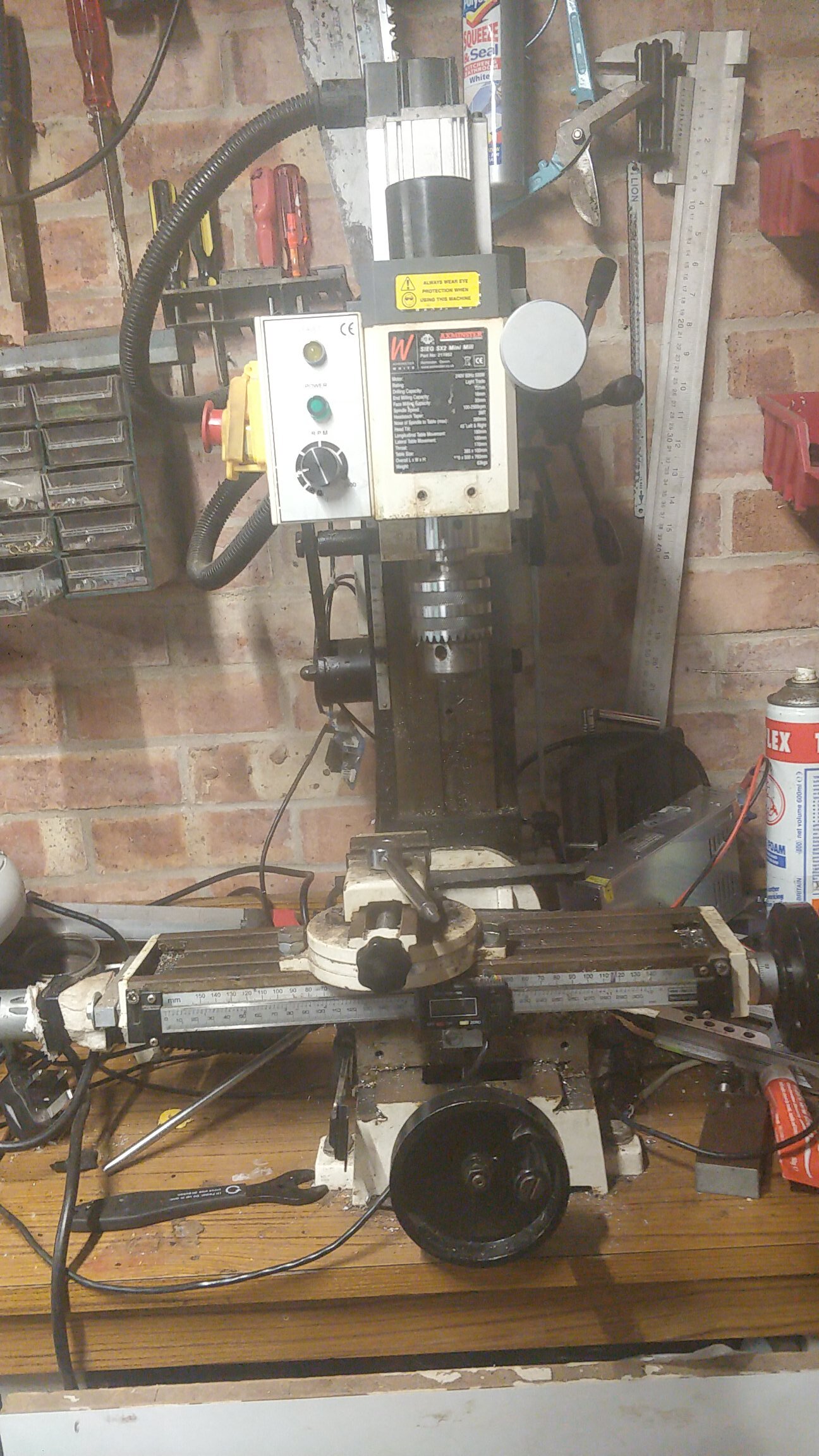
But first of all, I’ll get the mill finished .
Are you looking to CNC your Sieg SX2, I believe the table ways are identical?
I decided to make a short (ish) video to introduce my channel, where this has the above CNC conversion in it and running a test program.
The test program is running commands similar to G-Code on the Arduino in that I can just type functions like LineMill(parameters,0,0,0,0,0), CircleMill(parameters,0,0,0,0) which will lend itself well to applying G-Code once complete. So eventually I will be able to run G-Code directly from an SD card.
Feel free to ask questions.
Enjoy ODriving, I know I do
Kind regards,
Neil.
P.S. does anyone know how to embed YouTube videos? I used to be able to do it here, thank you.
Edit by Oskar: I edited your post to embed the youtube video.
I have a working 2 Axes (X & Y) mill running from the Arduino Mega 2560 (using the ASCII protocol and not Step/Dir).
Here is my latest video, please do not share just yet, it is unlisted and goes out on Friday 31st July. Just wanted to share it with you first.
This works really well, where all the backlash has been taken out before/during each move, feed speed is highly controllable and the accuracy and repeatability is exceptionally good.
I did have an issue (my fault I feel) with the ODrive 3.6 24v, where there was only a power light and no communication to both the Arduino or PC over USB, where I think I may have switched it all off in the middle something or other, I can’t be sure. Although just followed the online Firmware instructions, set it to DFU, re-applied all the parameters and was back in action. This is why I like the ODrive, plenty of online support .
I am currently typing this while the mill is cutting out the X-Axis perspex cover and powered only by Solar Energy, where the 230v motor is connected through a pure sine wave inverter to the same batteries as the ODrive. The system is stable at 12.4v.
So here is my latest video, take a look at the end test pattern… Enjoy…
That is a brilliant video, I love it. You have a really nice calm and understated style about your presentation. I have a renewed respect (as if it needed renewing) for real machinists after watching that.
Sadly, I doubt I have the required skill/experience/focus to replicate what you’ve done though. Hats off to you. And nice touch with the plexiglass cover over the workings.
Your arduino wiring stands out like a sore thumb though. Use some cables and connectors for gods sake
You have a new subscriber.
I remain skeptical of your thousand-hamster-wheel engine But I truly hope that you will prove me wrong
What did you do to calibrate out the backlash btw? From your test patterns you seem to have done it perfectly. Have you implemented that as part of the arduino code?
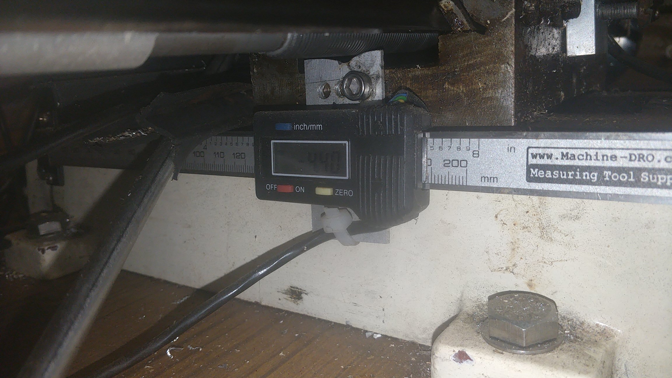
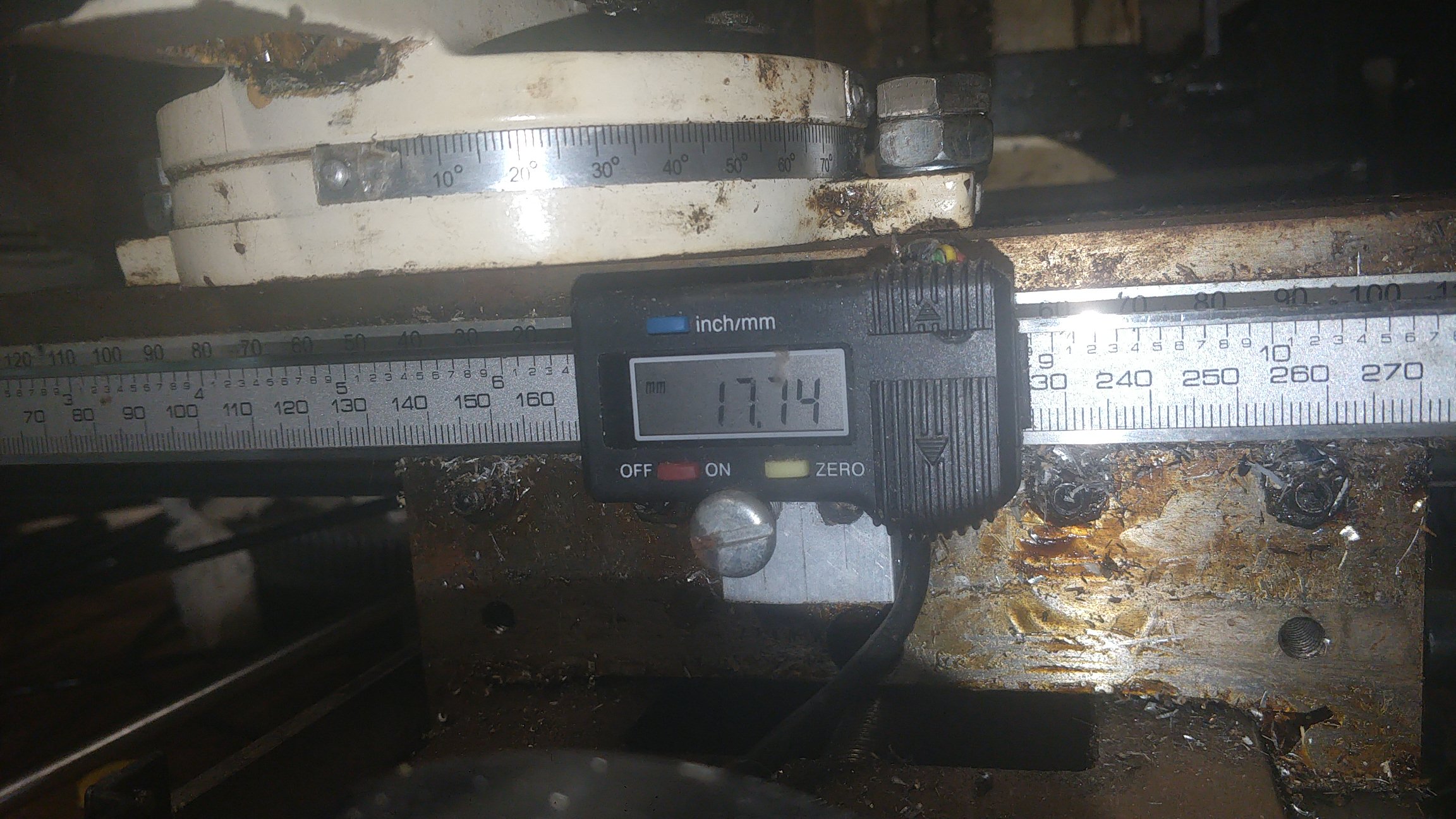
Also, how did you get your mill so well trammed? Mine’s as wonky as a witch’s beach hut compared to that.
Thank you for subscribing, the channel is growing well now .
Cheers, I never know how much detail to include as I want to engage everyone from beginner to seasoned tinkerer.
Yep, I agree, this is only temporary though, it’s all hidden in the very temporary MDF box at the mo, but it’s an improvement over using it on the breadboard. I’m concentrating more on the mill at the mo.
That’s a good idea, I never thought of hamsters …
I have a set value for both X and Y Axes where the backlash has a boolean value on each axis for whether it’s in or out and whenever there is a change of direction it takes out the backlash first at 300000 cps then carries on with the cut at required feed speed, it even works well with both tables locked (I accidentally found out) as there is lots of torque in the drive unit (maybe too much), but that could be of benefit (apart from increased wear) to keep the table solid on some parts. There is also a zero function that works well. Everything is controlled with the Arduino Mega 2560 and there is plenty of room for extra code. Also, the code is getting more like G-Code every time I tweak something, so there is GlobalMove function that runs all the movement and this is similar to G0, LineMill that controls all Axes, interpolating movement to reach a target position at the same time, while controlling feed speed. Then CircleMill controls CW/CCW direction, tool size, internal/external feature, arc length, feed speed, etc. So it’s all very busy .
I just ordered the X1-105 Long Table for the X-Axis also so I’ll have 460mm x 145mm of usable milling area.
Congrats, looks like your project is coming along nicely. Your videos are great, I’m sure you’ll start accumulating more subscribers as you go. You’ve made something a lot of us can relate to, I would like to do this too. Nice to see it working :).
Have you tried the anticogging algorithm? At the speeds you’re going, it might help with those tiny ripples in the plotter circles (it’s best at slow speeds)
Thank you @Riewert, the support on this forum and developers listening and helping here makes projects like this possible. I’m still a little shy on my videos, although try to put as much relevant info as possible and not too much to confuse people, glad you like them .
Hi @Wetmelon, I was reading through the anticogging algorithm and was considering it, although I won’t be milling at anywhere near these feed speeds, where all the part features are very smooth when running at normal milling speed (around 2mm/s), where the Arduino loop when sending commands to the ODrive is very efficient, around 165 times/second, so around 200 encoder counts per update (its 16384 encoder counts per mm) with velocity set to 32768 CPS. The circles were using a very large step at that speed (300,000 CPS), which is derived from the velocity rate and reduces as the velocity rate reduces.
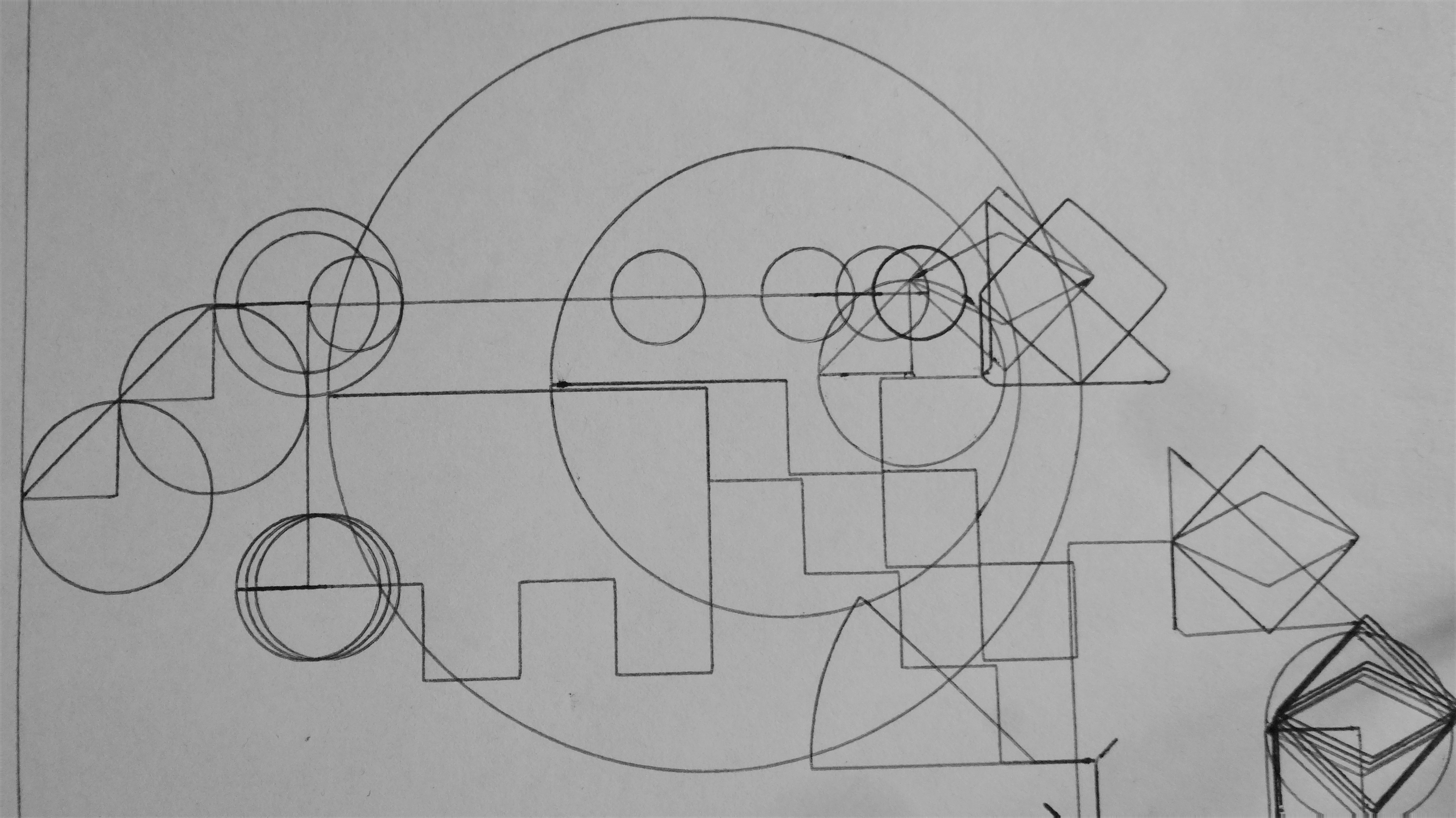
Here is a picture when I was testing and adjusting feed speeds at normal speed, where any deviation is from the pen nib moving around.
There is a GlobalMove function also (intentionally the same as G0 G-Code), although this just sends the final destination set-point and tracks encoder counts. I find the ASCII protocol is a lot more manageable for the Arduino than Step/Dir.
Hi Neil, another great and informative video, I can’t commend you enough for what you have achieved, I heard it said recently over a few beers; that all the great engineers have died, well after watching your video that claim would be so wrong!
Now lets get rid of those clamps!
Rather than me explain, just follow this.
Thank you for your kind words Jerry, it’s all passed down from my family, where my Dad is a cabinet maker, Granddad was a tool maker and Great Granddad a watchmaker, so have and use some of their tools.
Good idea on the clamps, I will need to go clamp-less eventually
I’m learning a lot just through trying things out, I’m really impressed by the ODrive system and know I can rely on it to follow all the commands given, it’s a very accurate, responsive and intuitive platform for so many different projects.
Hi, I just put the full sketch for the CNC ODrive control onto GitHub HERE.
I’m fairly new to GitHub, created an account in Feb 20 and only just uploaded the latest Sketch to it today.
The sketch is in it’s very early stages, so I need to weed it all out and change/remove old code that is not required/no longer functions due to changes. I thought I’d share it here as others may be able to use elements from that code.
Please excuse any code that is too simple, or suggest improvement, I am a self learner in programming Arduino C.
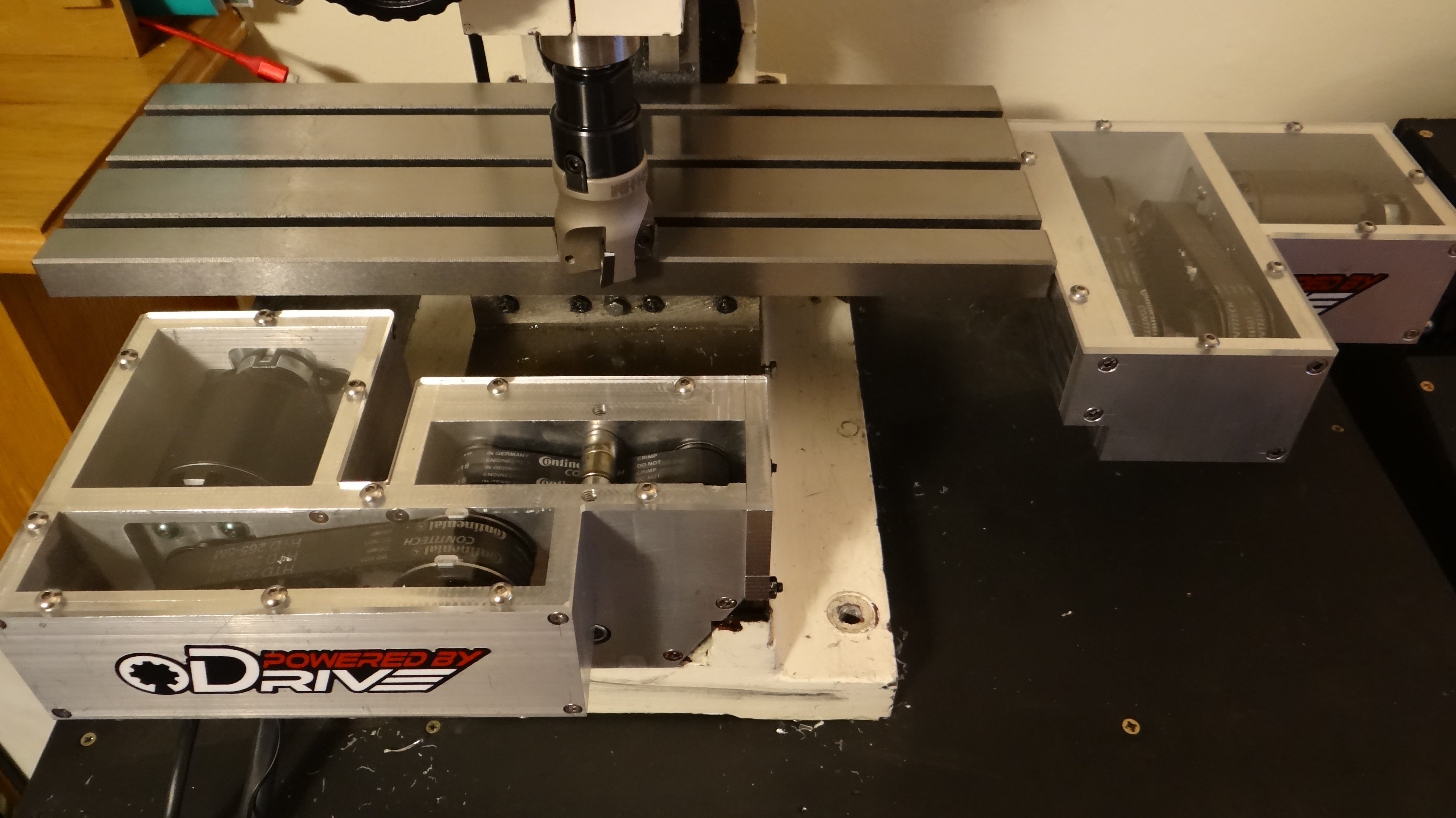
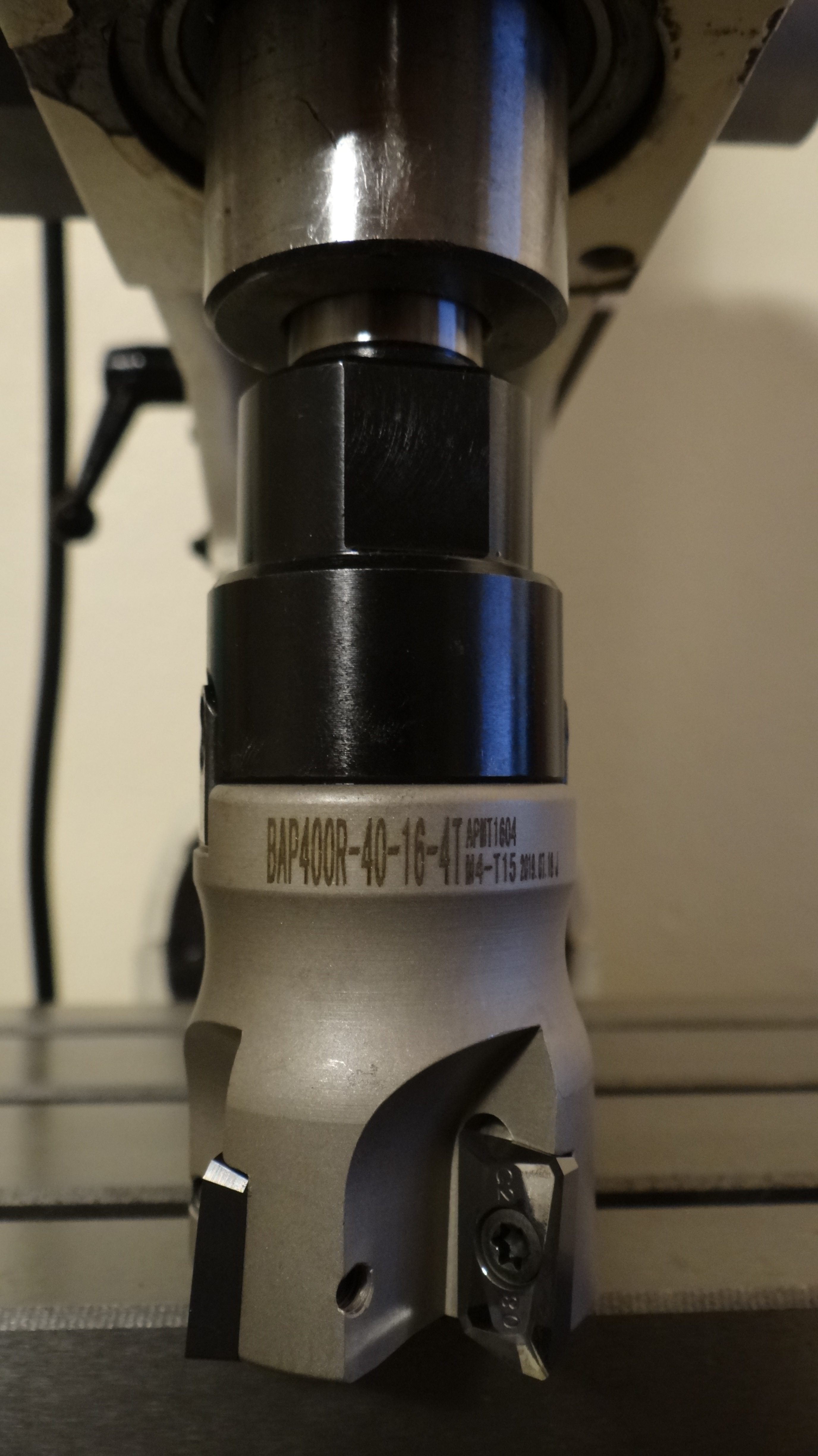
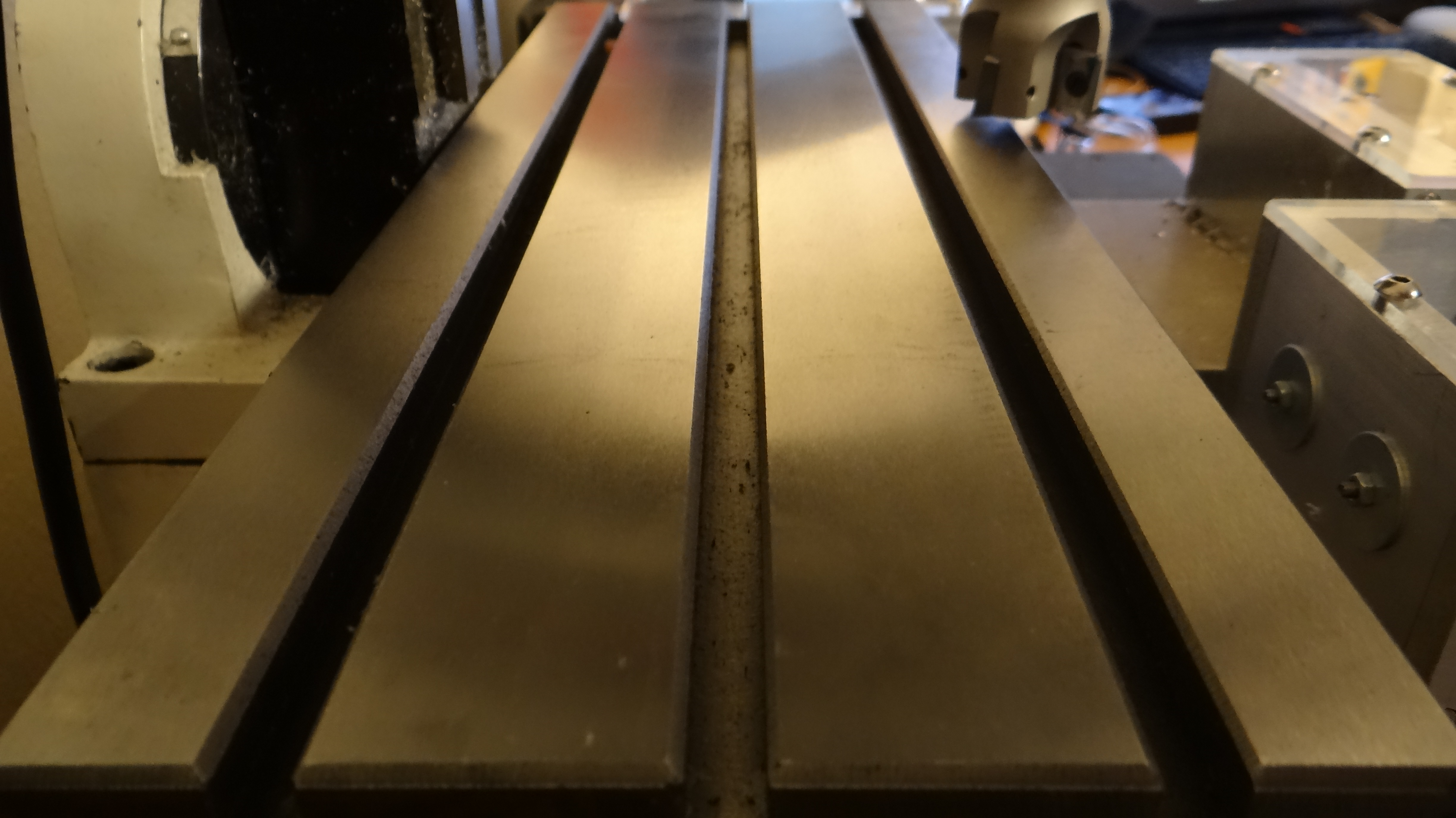
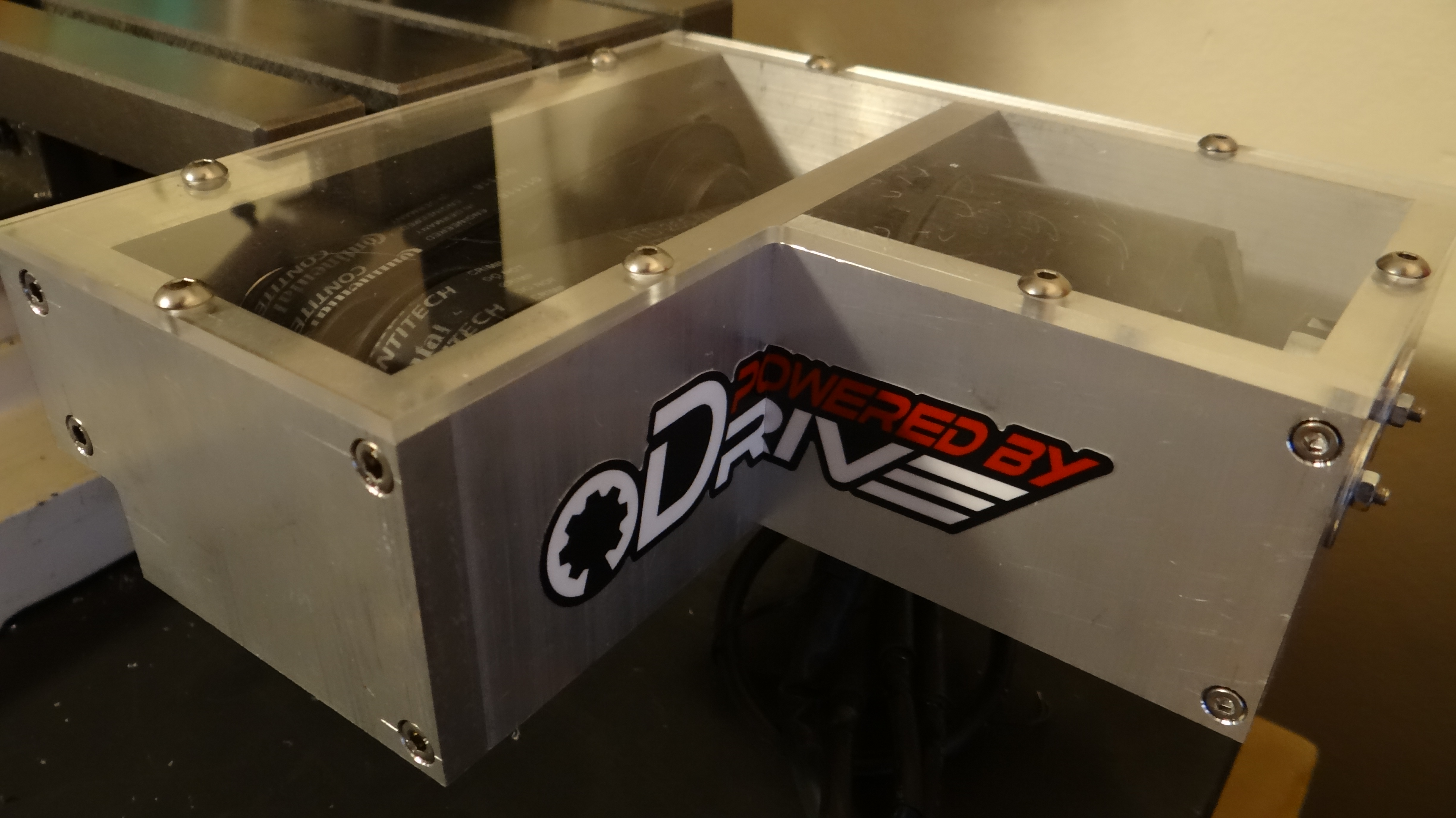
I have been a bit productive and now have a perspex cover on the X-Axis drive unit, milled by programming some CNC commands. A long table to increase capacity and allow multiple parts to be made in one go. Plus, a 40mm indexable fly cutter to parallel off parts before machining.
Everything is running very well and with tight tolerances, just need to make the drive unit base plates now with cable management to prevent damage to the cables:thinking:. It’s starting to look like a professional machine and run like one too. I can make things a lot quicker
There will be a small in between project coming up soon too, just a little gift for my nephew to test out the mill, along the lines of Minecraft ;-D, may post it here too.
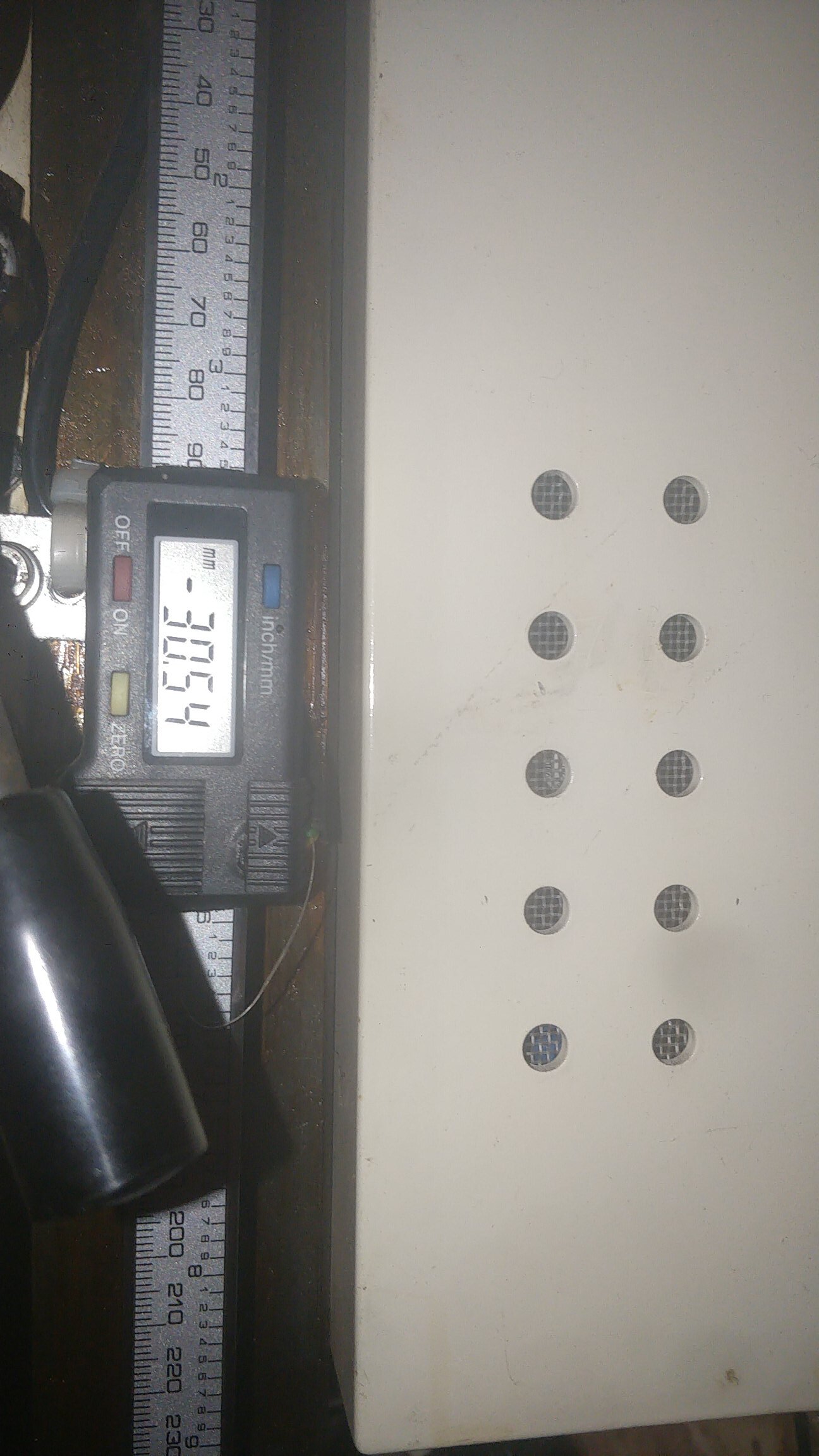
Here are some pics of the updated mill parts: -
Notice how the screws holding the perspex down are below the surface of the table (that was intentional .
The long table makes a huge difference, I’m sure it would fit on yours, although the new longer lead screw doesn’t reach the end of the table like the short tables screw did, probably to stop the table falling off lol. Still I have 300mm of usable travel on the X-Axis now .
I have a weeks leave next week too, so should get more done (should…). Watch this space.

 .
.


 But I truly hope that you will prove me wrong