So far I’ve been using straight end-mills which fit into a standard 3-jaw chuck (as supplied with the machine).
It works, but cutting anything fast is LOUD and rough. Maybe switching to a taper system would be better (if this is possible with the SX2)
That fly-cutter just looks badass, to use a (non-)technical term 
Where’d you get it? Arc Euro?
EDIT: So from the part no. in your pic I guess it’s this: https://www.shop-apt.co.uk/apt-90-face-mills-for-apkt-inserts/bap400r-50-22-4t-milling-cutter-for-apkt-1604-inserts-50mm-diameter-4-teeth-apt.html
But you still need 4x carbide inserts and a massive shank.
TBH that looks like a tool designed for a much more serious mill, rather than the piffling 500W mini-mills that we’ve got 
1 Like
I did this for many years with no real dramas, apart from slot cutting, which were all out of tolerance, hence the upgrade to MT2 ER20 collets, I will never go back now, even use collets for drilling.
Yes, its this one 060-282-00440 from HERE (Arc Euro)
And needs THIS Arbour 060-281-10216
Along with THESE Inserts 060-282-1604K10.
It’s good for very shallow fly cutting at low feed rates at 2k RPM, but not much else as my machine is currently only 150W brushed motor (soon to be 1.8kW BLDC from the ODrive 3.6 56v currently sitting in it’s box).
I darn’t cut too much with i at the moment as those Nylon gears will look like a grannies mouth after midnight 
2 Likes
 … <3
… <3
1 Like
Hi all,
I am still here and plugging away at the CNC machine and other projects.
Well done to all those at ODrive and those that support them on here, this is a fantastic system that I can rely on for CNC work. Thank you.
Here is what it looks like now, with the new long table, where it’s proving to be very valuable, especially with all that time-saving.
Sorry @Jerry.Atrick I haven’t yet tried the tape and glue holding solution yet (I’m not that brave, but have been looking into slide clamps as this would probably work best with my long table.
Well here’s the latest video (hope you enjoy): -

Please feel free to comment and suggest anything you feel is missing or you liked.
Thank you,
Kind regards,
Neil.
5 Likes
Great Stuff Neil!! Really like what you’ve done with your Odrive!
1 Like
Hi Neil, another really good video! Cant wait to see the Z axis, and the BLDC motor 
So do you (personally) cut aluminum with no lube or compressed air, or is it because it was so thin?
Do you have a particular BLDC Motor in mind for the spindle ?
Kind regards Jerry.
1 Like
Hi Jerry,
Thank you.
I normally spray some cutting compound on the tip or use the wax stuff on the bit, although find it best to show milling without lubricant for video’s (probably setting a bad example), I am a little guilty of not using lube while in the house (not everyone is a fan of the smell like I am, reminds me of my dad and grandads shed ).
The BLDC motor for both the spindle and Z-Axis are the D5065-270KV (same as X and Y), where I don’t think I’ll need to use the full 1800W power for the spindle. I think it’ll be one of the most powerful home CNC’s around  . I have tried stopping the X-Axis while it was milling (just to see if I could) and it carried on with no effect on the part, with the machine lifting the whole table up on one side, hehe.
I already have both motors and a ODrive 3.6 at 56v, although the plan is to run it at 12v like the others, it’s very efficient.
Kind regards,
Neil.
Hi, Just thought I’d share this as was asked in Discord by @Wetmelon.
Both M0 and M1 at rest are showing this constantly and are very stable tracking positions with no overshoot, does this mean all is good with my tuning?
If so, the tuning method under the document section works a treat 
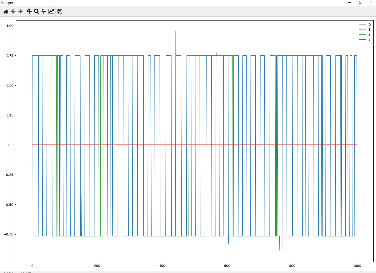
What are the signals and units on that plot? Label your axes and legend. D-minus must try harder 
+/- 0.75 oscillation of… what? Position in degrees? (can’t be counts…)
Ah yes, as follows: -
0 = Position of M0
1 = Demanded Position of M0
2 = Position of M1
3 = Demanded Position of M1
Was aiming for a B+ at least.
Can you label the axes on the plot itself?
Here’s the command I use: -
start_liveplotter(lambda:[odrv0.axis0.encoder.pos_estimate, odrv0.axis0.controller.pos_setpoint, odrv0.axis1.encoder.pos_estimate, odrv0.axis1.controller.pos_setpoint])
1 Like
So the units are encoder counts, then?
How is it possible to have following error of 3/4 of a count?
I mean, very impressive if so!
How is it possible to have following error of 3/4 of a count?
Very good question, I hadn’t thought of it before.
Is it because they are estimates, similar to how steppers have multiple steps between each pole. I am guessing the ODrive knows when the pulses happen so it can estimate exactly where it is, but not from the encoder counts (that’s just for encoder to motor angular syncing), instead from the fine PWM control. So 8192 counts per revolution of the encoder, although the motor control has 4 times more position control, so 32768 positions per revolution.
@Wetmelon / @madcowswe, are we way off here ;-).
Thanks
1 Like
The amt102 encoders have 2048 ppr, or positions. The cpr is that number times the quadrature counting factor(x4 in this case). So 8192 counts.
Hi @Roiki1, Yes, hence 8192 counts per revolution for the AMT102, where the plot above seems to show 0.25 motor steps per count, hence 32768 motor steps (resolution of PWM control) per 1 revolution.
So 2048 ppr x 4 (quadrature from A, B) = 8192 cpr, then 8192 cpr x 4 motor steps per count = 32768.
I suppose this is to allow for much higher counting encoders. I’m wondering what the resolution of the motor PWM signal is?
I’m still a bit confused. How could you divide the count between individual counts to 4 parts when you have no reference to do so? The math only knows a movement happens when one bit flips?
So, my thoughts are: Say the A output of AMT102 goes positive as the motor is rotating slowly (3 x 120º phase shifted sine waves rotating slowly), and looking at 1 sine wave, there were 32768 positions for that sine wave per 1 period (cycle); then there would be 4 phase positions of that sine wave before the B output of the AMT102 goes positive.
Therefore, the ODrive knows where the Encoder counts are in relation to phase changes of the motor coils, so it would be able to move between encoder counts.
Or put differently: -
- Motor Phase = 0, Quadrature A = 0, Quadrature B = 0
- Motor Phase = 01, Quadrature A = 1, Quadrature B = 0
- Motor Phase = 02, Quadrature A = 1, Quadrature B = 0
- Motor Phase = 03, Quadrature A = 1, Quadrature B = 0
- Motor Phase = 04, Quadrature A = 1, Quadrature B = 0
- Motor Phase = 05, Quadrature A = 1, Quadrature B = 1
- Motor Phase = 06, Quadrature A = 1, Quadrature B = 1
- Motor Phase = 07, Quadrature A = 1, Quadrature B = 1
- Motor Phase = 08, Quadrature A = 1, Quadrature B = 1
- Motor Phase = 09, Quadrature A = 0, Quadrature B = 1
- Motor Phase = 10, Quadrature A = 0, Quadrature B = 1
- Motor Phase = 11, Quadrature A = 0, Quadrature B = 1
- Motor Phase = 12, Quadrature A = 0, Quadrature B = 1
I may be going off at a tangent, but that is how I see it working in my head. Hope that helps. This may need clarifying from the ODrive guru’s
The position/velocity used for control comes from the estimator in encoder.cpp, which is a PLL that functions as a tracking filter. The key is that pos_estimate is vel_estimate * time_elapsed * gain1 + number of counts since last update * gain2. If you want to see the actual raw encoder position, you can use odrv0.axisX.encoder.shadow_count.
There is interpolation, but it is not intentionally 1/4 count or anything like that. It seems to me that your 0.75 counts is a numerical artifact of the position estimation
1 Like
Ahh, that makes a lot of sense, hence why it is only an estimate and not a true value. There are a lot of variables there to make up the pos_estimate.
I will put shadow_count into the live plotter and look at that data instead.
So from this, is it best for the my Arduino to track pos_estimate or shadow_count? not that it would make much difference.
Thank you for posting, it could have gone down a rabbit hole