No problem! If you are using the Arduino for DRO purposes, I’d probably stick with pos_estimate, just because it’ll be marginally less noisy.
Yeah, I’ll stick with pos_estimate.
The Arduino is a Mega 2560 and it runs the ODrive using the ASCII protocol, shows DRO info and will convert G-Code (hopefully) from an SD Card.
I am currently writing the sketch in accordance with the Mach4 reference and Fusion 360 standard Post Processing G-Code, so will be able to post process in Fusion 360, transfer to SD card then let the Arduino and ODrive do their thing 
It’s currently working with G00 and G01, where G02/03 are a little head scratching 
I suspected that might be it 
But still, that means that @Dev255 really does have less than one count of steady-state error, which is pretty impressive since this is for a CNC machine. It probably does mean that the ODrive is responding in sub-count resolution (i.e. the applied torque will be dependent on the average amount of time that the error is positive or negative) - I wonder if it would be possible to command sub-count positions, by driving this average to a particular value?
(it would still have to oscillate by at least +/- 1 count though, so I don’t know if controlling the average position inside of that is useful)
But in any case, it’s pretty impressive that the 8192cpr encoder is the sole bottleneck to positioning accuracy. @Dev255 What’s 1/8192 rev in terms of microns at the cutting tool?
A* for practical! But theory (like mine) needs work. 
Pfft, mere µm, it’s 61nm per encoder count  , not bad for a home mill, although can’t guaranteee anywhere near that accuracy with the rigidity of the machine. So 2 revolutions per 1mm being 1/16384.
No point in being perfect 

2 Likes
I have now successfully tested out my programming skills by machining out this part.

The Arduino Mega 2560 now accepts standard G-Code to churn out parts. Now all I need is an Z Axis and a spindle motor fitted, where I have the pulleys and am currently 3D CAD’ding the Z-Axis and Spindle components. I’m going with a 1:1 ratio on the spindle motor and may even add a small flywheel to the spindle shaft as a torque reservoir, hmmm…
With the G-Code, admittedly, I have only programmed G00, G01, G02 and G03, although 02 & 03 are the hardest to achieve, where I had to get my head back in to trigonometry and work out arc radians, feed speeds at different radii and all manor of other calculations and conundrums to make it all work, including maintaining backlash control, hence the time taken to get to this point.
Hope you like the latest video.
P.S. I used lubricant on this one @Jerry.Atrick ![]()
2 Likes
Hi all,
A new video ![]() , I am so confident with the ODrive system that I now leave it to run in its box.
, I am so confident with the ODrive system that I now leave it to run in its box.
I’m looking forward to making the Z-Axis and just have it make stuff on its own.
This video is about using a septic tank aeration pump to blow the chips away, it works really well, but you do need a corner to blast it into.
The part I’m making is a Machine Squared End Stop, so it’s at true 90 every time it’s placed down.
Hope you enjoy.

Happy ODriving,
Neil.
1 Like
lol. when I saw that I was thinking of fish tanks, not septic tanks, and thought no way could an aeration pump be powerful enough for that! 
I didn’t know septic tank aeration pumps were a thing… sounds like a smelly business!
1 Like
The pump just smells a little of rubber from the diaphragm, but luckily not the smelly one, although I don’t smell the harm in buying a second hand model 
1 Like
Hi Neil, another great episode!
And no question as the blower sure does it’s job; kudos to you. I doubt that anyone else would have thought this creatively
Maybe you can get another blower unit, and make is SUCK, that will quietly remove all those pesky chips 
Regards Jerry.
PS: maybe one day soon I will ask you about speeds and feeds, as it appears you know what you are really doing! “if that’s okay”
1 Like
Hi Jerry, why thank you kind sir,
I’m not sure it could be used to suck all those chips up, hmmm, maybe a catch couling that collects them up .
Hmmm, Feeds ‘n’ Speeds… I think like most hobbyists I just roughly muddle through if I’m honest and listen to the machine.
I didn’t up until now look at feeds and speeds in any great depth, just had my tools on a spreadsheet with rough calculations. Before responding to this I had a good think and re-work of this spreadsheet so you and possibly others could have a copy and tweak it to their desires.
Download from here (I just uploaded it): -
Excel Feeds and Speeds Calculator
On the spreadsheet you can adjust machine load, machine capability, spindle speed and Depth of Cut to get the ideal Feed Speed for each tool.
Feel free to re-distribute if you feel this may help others, or tell me it’s pish if you find it useless .
Hope that helps.
Kind regards,
Neil.
P.S. I may even put this as a feature in the Arduino sketch so that I don’t have to calculate it, again hmmmmm.
1 Like
Hi Neil, firstly thank you for taking the time to reply, I always enjoy your response 
Secondly; I’m not sure what a “catch couling” is but I’m sure you could make it work
Thirdly; Thank you for the speeds and feed document, its well set out and even my old brain can attempt to follow it, I will give it a go: thanks again.
Great Idea, with the Arduino sketch.
Regards Jerry.
HI Neil, What’s going on here then?
Good Question!
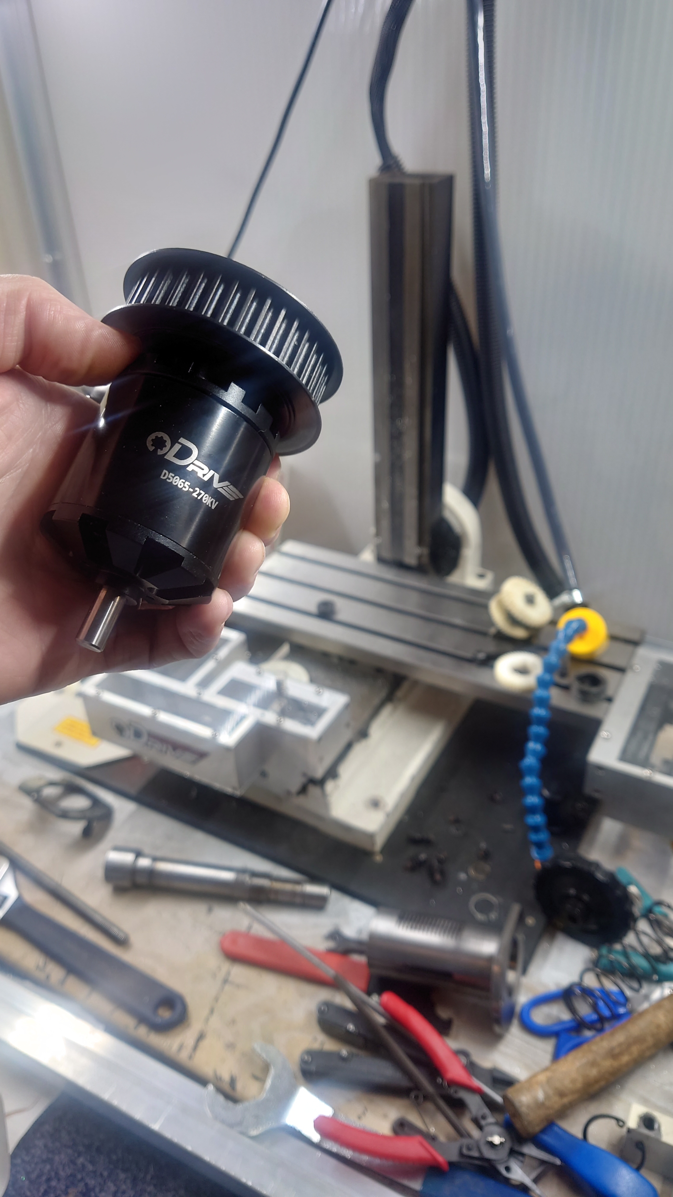
Image 1/ looks like the start of a spindle; with a large pulley on it
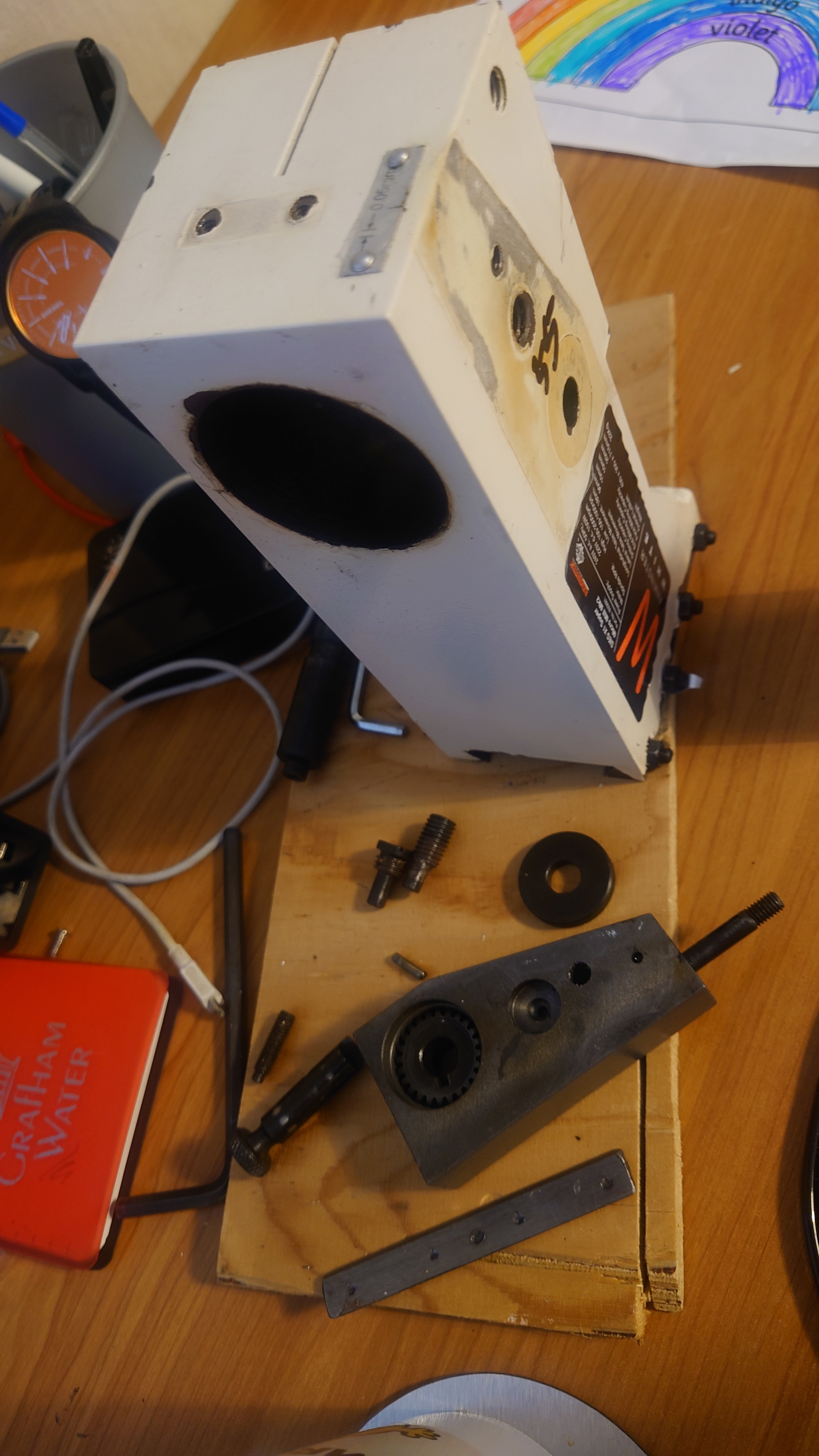
Image 2/ looks like something was cooked " so I have NO Idea 
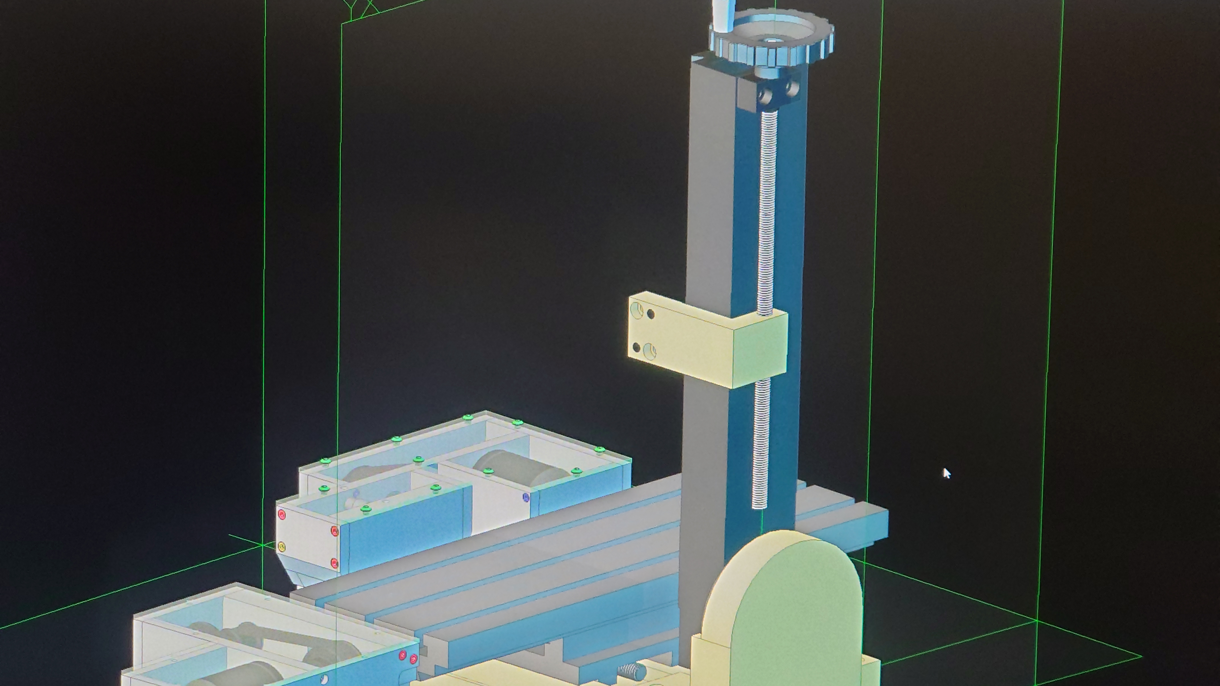
Image 3/ could this be the layout and plans for the Z axis “lets hope so” 
I suppose you will lets us all know soon.
Always good to see your posts.
Jerry 
2 Likes
Thank you Jerry,
Image 1 is the start of the spindle pulley, where both spindle and motor pulleys are 40 teeth, as there is plenty of power in the motor and I’d like to get full speed 12,000 + RPM with 48v, although will be running from 12v initially, so 3240 @ 12v (minus small voltage drop through MOSFET’s). The original motor is a brushed 240V PWM controlled 150W motor (2000RPM at spindle max). so 1800W Brushless should be a small (ish) improvement .
I’ve gone for large pulley’s as there is more contact with less load on the belt and it won’t be travelling as fast, plus the spindle end requires a 20mm bore with a 4mm keyway (ordered from beltingonline.com), I was going to do this, but they can do it for a couple of ££.
Image 2 does look burned out, although it just needs a clean up, I’ve stripped it right down to transfer it over to CAD and also to replace the bearings (the seals had broken down and it was getting noisy). I’ve since ordered 2 brand new high end, high load, deep groove bearings that can handle 20,000 RPM, so should be mad enough for the job.
Image 3 is the start of putting everything on CAD, where I plan to do both the Z-Axis and spindle at the same time. Plus I need to do this so I can get orders in before UK Lockdown, hopefully.
Also, I won’t be putting a flywheel on as there will be plenty of torque in the ODrive motor and I fear hugely damaged parts/bits should the thing keep running following a crash… Hopefully not though (touch wood).
Ah, and I’m looking at adding a 70mm block between the base and the riser as there is 50mm of unused Z-Axis track, plus it would allow the Y-Axis to have around 15mm of extra travel.
I will keep thee posted 
Kind regards,
Neil.
2 Likes
Hi Neil, thanks for the detail in explanation, you have some very creative ideas, and I wait in anticipation to see what you do next
As for the spindle; I toyed with the idea of using one of these
But it wasn’t to be (bad health and finances don’t mix) anyways I look forward to your next update.
Regards Jerry 
Hi Jerry,
No dramas, father teach
Hmmm, Well… I’m really considering using the 56v ODrive as the main controllers in my MGF project, as @towen mentioned, it’s going to be difficult to get all the 24 motors running together, where with the ODrive it’s very tuneable and gives plenty of fast feedback, so I will be able to maintain torque output through current control (hopefully, we will see ). That means I will need 12 x 56v ODrives for the job and create a bespoke heatsink that spans across all MOSFETs with cooling. If I make these, it will be easy to produce a good number of them on my machine in one go
Part of using the 56v ODrive for the spindle motor is to see how controllable it is under velocity control to see if it’s a viable option for the MGF. I will then be able to stick a big ODrive sticker on the car (if all works well or maybe not if all blows up in an uncontrollable catastrophic failure .)
As for the mill so far, it’s back together with new bearings (although getting hot when running with a little pre-loading) and it has made it far quieter, everything is much tighter/ridgid, so should be able to cut much deeper and more confidently. as in the pictures below, I’m looking at machining out the spindle motor housing from 1 block of aluminium, so the machine needs to be up to the challenge.
Also, there will be a rotary encoder on the spindle motor for the machine tapping party trick.
Wow, these are powerful motors, they are a little expensive, I’m having to buy something every couple of months and do loads of research to reduce cost, that’s probably half my time at the moment. What machine would you put this on? You would need a monster controller on it too.

Hope you feel well.
Kind regards,
Neil.
2 Likes
Hi Niel,
Nice work, can’t say it often enough!
As for the construction advice though… I don’t like that they are two separate things. Can you combine the spindle motor? It might vibrate etc and pulling it to the other motor will make it nicer balanced I think?!
1 Like
Hi Quintin,
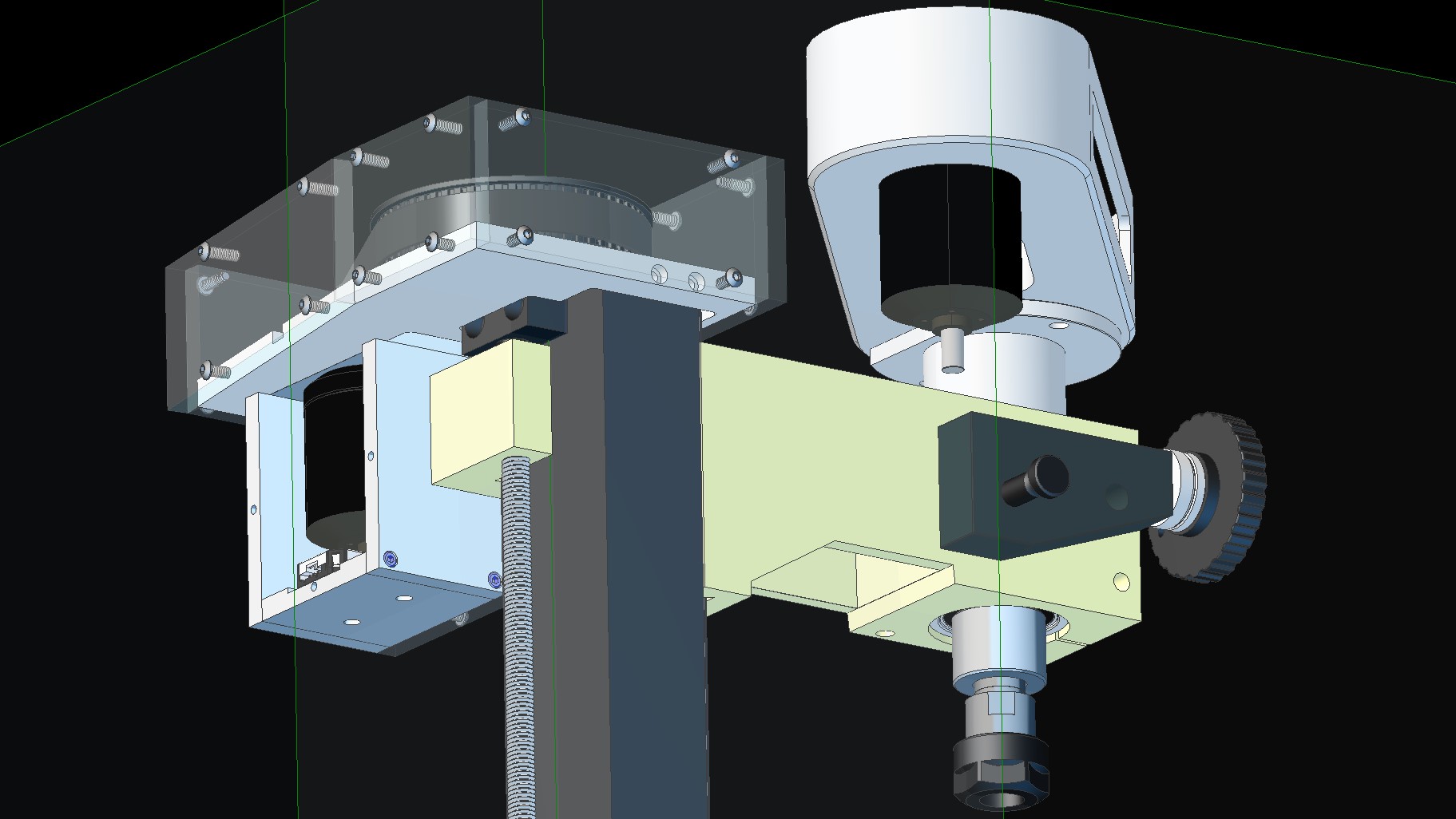
Thank you, I played with this design quite a lot, where I’m toying with the idea of milling the Z-Axis enclosure from one piece of aluminium, although this is expensive if something goes wrong.
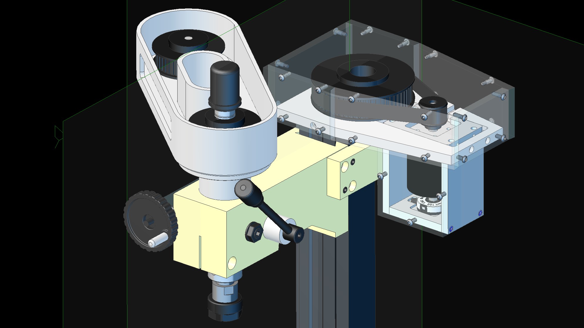
I’ve had to put the spindle motor on that side and far from the spindle as it would interfere with all the manual control elements, such as the manual quill lowering handle on one side and the fine control knob on the other, where I also wanted the motor underslung on both spindle motor and Z-Axis motor as the height is restricted in the cabinet I put together (I’m looking at raising the Z-Axis riser as there is around 50mm of unused travel at the bottom).
I’m also designing the spindle motor housing into a heatsink as this will probably get a little warm when running.
Can you see another option? Happy for suggestions as it’s still in the design phase.
Hi Niel,
Thx for your additional considerations. Makes more sense now indeed. Could you shorten the belts to perhaps get less of a vibrating bending on the spindle?
I think that making the housing of one piece of alu is counter productive. You don’t need the stiffness (belt is less stiff anyways) and would gain from the friction of bolted parts to lower the vibration with multi parts. Save the money although I think I’ll be so impressed with a movie of you, the mill and that one piece of alu ;-)!
Hi Quintin,
No problem, I did toy with the idea of shorter 375mm belts (that actually arrived today) for the spindle making 87mm centre distances with 40mm pulleys, although this would mean the motor would sit above the belt housing.
I agree, the bolting option would definitely be the cheapest way to go, although chose this way for a few reasons, mainly for how it would look both machining the part out and once installed, plus I get to see how my new chip extraction pump holds up to pocket milling.
The single block of alu (40mm x 300 x 100) will cost around £32 for 5083 Grade (one of the strongest non-heat treatable alu materials) where it will only weigh around 860 grams. So with motor pulleys and housing should only come to 2.4kg, so not too much strain on the quill. I’ve purposefully put the centre feature in to increase rigidity though.
I think the main driver for design, as it’s on YouTube is the looks, although it’s a very capable machine now with all the mods.