Possible Cheap Ground Loop solution for UART?

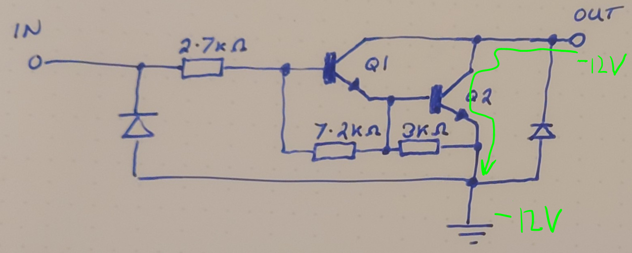
ULN2003A Darlington pair array…

Bear with me…

I love using these for protection in many circuits and have used them for all manor of things including converting RS232 to higher voltage (12v) RS485 for distant CCTV applications (PELCO D protocol works well), small DC motor drivers, Stepper drivers, etc, etc. Where you can parallel all of the 7 internal drivers for a max of 3.5A. Plus they are a cheap (£0.42) frangible component (although doesn’t offer full electrical isolation like an Opto-Isolator, but does offer a good degree of protection and can handle high speed serial such as 115200 bps).

The ULN2003A’s can handle up to 30v on their input pins, sink 50v on the outputs, have suppression diodes on both input and output and are fast switching (max 1µs both rise and fall (0.25µs typical)).

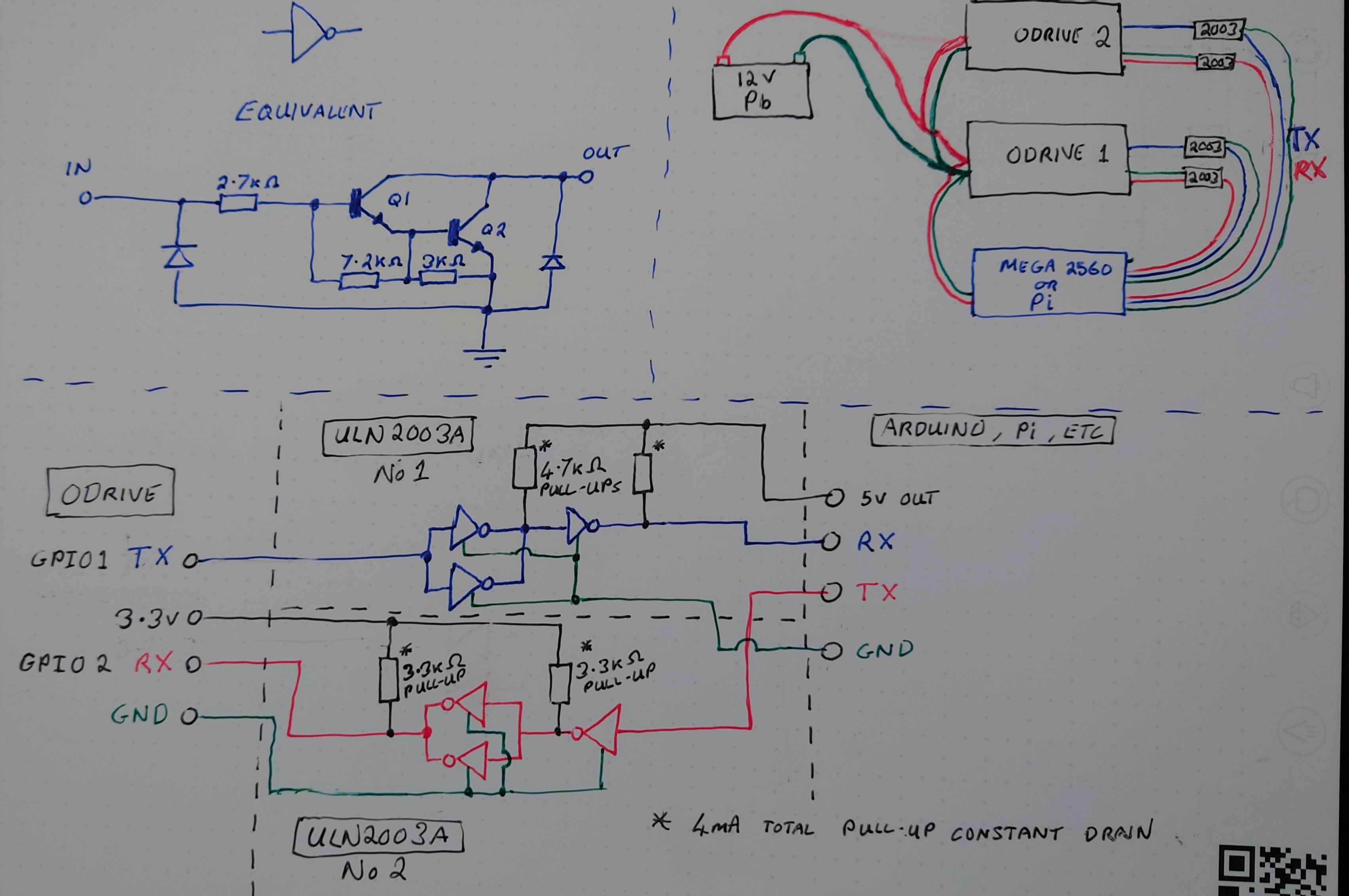
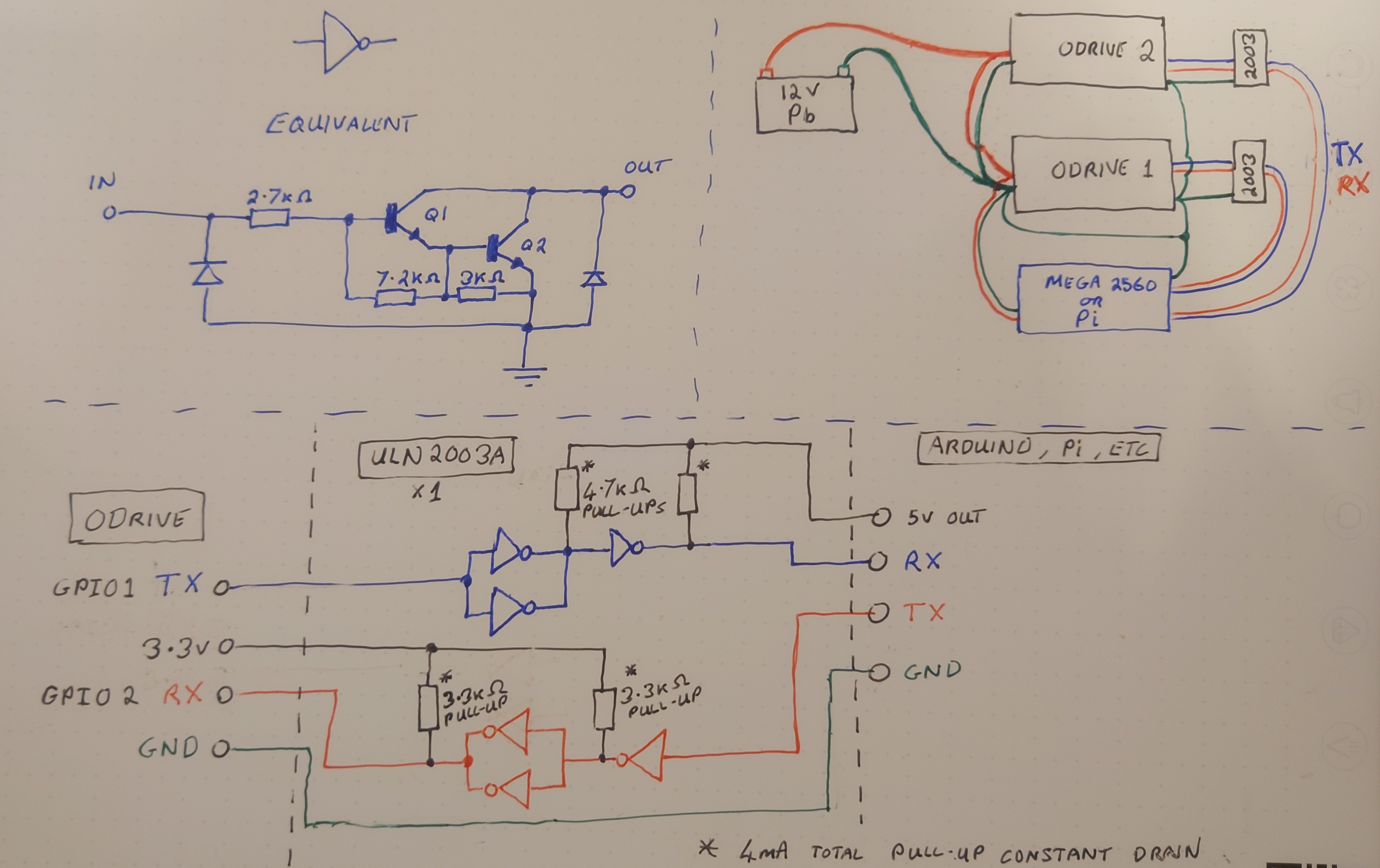
Please forgive the scribblings, but here’s the thought…


Note: Both Positive and Negative wires were supposed to go to ODrive 1 (it was late :sleeping:).

So, for my CNC project I am almost at the point of connecting 2 x ODrives to a 12v battery source and will have both of these directly connected to an Arduino Mega (Serial 1 & 2). Ground loop nightmare?

Well, for power, the battery (12v Lead Acid) will have 8 AWG cable to the first ODrive, then 8 AWG cable from the first to the second ODrive (a few cm’s), power will also go directly from the first ODrive (the one having the highest current draw (spindle motor)) to the Arduino Mega (again short run, although not so drastic as low current) so that any voltage drop is followed by all boards at almost the same rate, minimising current rush between boards. Star earthing will be abundant too…

For Serial comms (for extra protection), use a trusted ULN2003A as shown, where you could just use 1 device for both ODrives as there are 7 darlington pairs, although just doubling up for extra protection (doubling up on those suppression diodes). I’ll use the 5v from the Arduino and 3.3v from the ODrive just to ensure the levels are matched to their own device.

I’ve used these chips for years to great effect, although from another angle you may see something I’ve missed.

What are your thoughts on this one?
Maybe even use them for logic level matching… :thinking:
Delete if you think this is completely barmy. I will be testing it out though :crazy_face:

Happy ODriving,

Neil.

P.S. This topic is similar to: -
Understanding the risk of a ground loop
OTS Opto-Isolator for UART Ground Loop
Ground Loops (from ODrive documents).

3 Likes

Looks great for protecting against short circuits to 5V, or even shorts to motor phases or power supplies, and anything else that can cause actual smoke… But I can’t see how it protects the communications against ground loops, since it is still 3.3V single-ended signalling, and the grounds are still connected? :thinking:

Just use CAN. :stuck_out_tongue_closed_eyes:

1 Like

Hi @towen,

My thought’s where from the basis of one cheap component that’s easily replaced in a DIP socket should a spike/Ground Loop current rush occur and be able to maintain the high speed UART connection, as opposed to a relatively expensive Opto-Isolator.

They are very resilient. :muscle:

Or that one, although some don’t have this option.:unamused:

Ah, but the ground loops potential is reduced by taking the development boards regulator input directly from the DC bus at the ODrive’s Power input (in my case, the one with the highest demand), as opposed to the battery or PSU output. So the inductive element of the cable is before the regulator and ODrive, not between them, reducing the potential difference between seperate board earths. Plus, the earths are interconnected, not left to one point of failure.

I guess most projects with high power motors attached will suffer vibration, therefore you would want as much protection as possible. (last edit, honest :wink: )

Hmm, so you’re saying that the ground for the Pi is referenced from the negative rail of the ODrive, which itself may be waggling about in the 10kHz-1MHz range
That’s all well and good if the Pi (Or arduino) and ODrive are close together and powered only by the one battery, but it falls down if:

  • There is any parasitic capacitance between the Pi and Earth - it cannot follow the voltage ripple of the ODrive exactly, due to this
    (for whatever reason I refer to it as Ground/GND when talking about the reference point in circuit analysis, and “Earth” when talking about the electrical potential of our Planet, and protective conductors therefor, to prevent electrocution)
  • If the cables between Pi and ODrive are very long, then they will have a high inductance and so amplify the effect of the parasitic capacitance. They will also have high resistance and cause a voltage drop due to the Pi’s own power consumption.
  • If there is any other power source or ground present, such as an external power supply or USB connection to the Pi

Also, the above has nothing to do with your buffer arrangement. :stuck_out_tongue:
& I don’t know what vibration has to do with the price of fish? :thinking:

That said, it’s quite common in Automotive applications to have ‘Ground’ always connected to the metal chassis, and even to use that as the actual return path. So the alternator has one wire, with the other side being bolted to the metal, and same for the battery, starter motor, lights etc.
This makes for quite a nice “distributed ground”, and also helps confine any EMC issues to inside the vehicle by way of a Faraday cage.
But even then, they needed CAN bus, that’s why it was invented. :stuck_out_tongue:

Yeah, so this is to prevent damage, but the normal symptom of a ground loop is that communications (especially UARTs & USB) get spurious intermittent faults & dropouts. It’s pretty extreme for them to cause actual damage. (although it would be the CAN transceiver that goes bang in this situation, and they are as cheap as transistor arrays)

The differential signalling, CRC & retransmission afforded by CAN only protect the integrity of the signal - it does not protect against damage caused by extreme ground loops, unless you also use an optoisolator.

EDIT: Ah, I see what you mean now when you said “vibration”. You mean if the ground wire between the ODrive and battery were to shake loose, then the Arduino can go up in smoke because it is now conducting motor currents after the TX/RX wires are suddenly 12V.
Your arrangement might well protect against that, but mainly because the Arduino is not separately connected back to the battery.

1 Like

I think a picture showing a concrete example is probably better than a bunch of assertions.

So the below analysis skips a little bit of detail about how the signal and power grounds are connected internal to the ODrive, and the voltage levels may not be exactly 12V, but something a bit different.
But I hope it shows a concrete example of why the grounds being connected under the darlington buffers form a ground loop, and an example of how that may cause problems still.

Let’s call the GND at ODrive1 the reference 0V. Lets say ODrive 2 is switching a bunch of current, which will draw hard pulses of current from the DC input, which will generate voltage spikes across the parasitic inductance, and for small wire loops this spike may be very short lived but might be quite large peak still.
I have drawn this as the left inductance in the picture below. For completeness I drew some inductance across the signal GND wire on the right also to indicate that that wire is cannot really clamp the signal gnd to 0V because of the fairly low impedance connection internal to to the ODrive.

So the GND node at ODrive2’s driver chips could go +/- 12V with respect to the ODrive1 reference which is also the reference for the Arduino. The issue here is that the driver makes a low impedance drive-low path when driving the UART line back to the Arduino, meaning it can drive the arduino pin hard to -12V, which could damage the arduino.

There may be some other combinations of parasitic inductance and voltages that could damage other things, it really depends on the setup. But overall the key takeaway is that if the GND loop (which contains high current pulsing DC-) isn’t completely broken, it can be hard to nail down all possible places that voltage excursions may take place.
I would recommend using an actual isolator (that breaks the GND loop). My current favorite is the TI ISO776xF series.

Edit: one way that may leverage the buffer’s increased voltage input tolerance without adding much other issues could be to just put an Rx buffer in front of the GPIO on every device (each ODrive, the arduino). Then it would be pretty similar to an unprotected system, except the buffer will be the one to eat the voltage pulses.
I’m assuming here that the STM32’s output buffers can handle some spiky currents, and I hope that’s a good assumption. If not, I suppose you could buffer the output AND input of every device. Though at that point maybe an isolator is less hassle.

3 Likes

Or this one…

Where there are 3.3kohm series resistors on the ODrive would limit the current flow, plus earths are now not common.

Although as you mentioned the ISO776xF is a good solution, or part off the ODrive V4? :wink:

2 Likes

Hm this is indeed unlikely to cause any damage across the UART lines, that’s good!
The main issue now is that you can get spurious data edges from inductive noise in the GNDs. You could add an RC lowpass filter on the inputs to try and fix that.

But yeah indeed the isolators solve the problem with not much work. Of course if this is a challenge to make what you have at home work, then that’s cool.
Yes those isolators is what we are looking to use on ODrive v4.

2 Likes

I think as you said the best solution is the ISO776xF as it also handles up to 100Mbps.

I think I’ll give it a gentle go, while slowly increasing the current demand so nothing pops ;-), what was the warranty again :smiley:

Can’t wait for ODrive v4.

2 Likes

It’s been a while but is there any off the shelf isolator on the market already?

You can just buy a digital isolator off Amazon - e.g. Amazon.com

1 Like