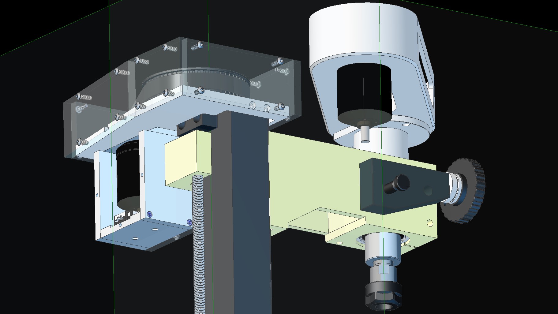
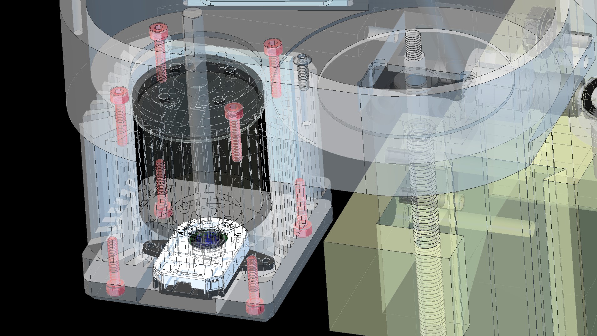
Image 1 is the start of the spindle pulley, where both spindle and motor pulleys are 40 teeth, as there is plenty of power in the motor and I’d like to get full speed 12,000 + RPM with 48v, although will be running from 12v initially, so 3240 @ 12v (minus small voltage drop through MOSFET’s). The original motor is a brushed 240V PWM controlled 150W motor (2000RPM at spindle max). so 1800W Brushless should be a small (ish) improvement .
I’ve gone for large pulley’s as there is more contact with less load on the belt and it won’t be travelling as fast, plus the spindle end requires a 20mm bore with a 4mm keyway (ordered from beltingonline.com), I was going to do this, but they can do it for a couple of ££.
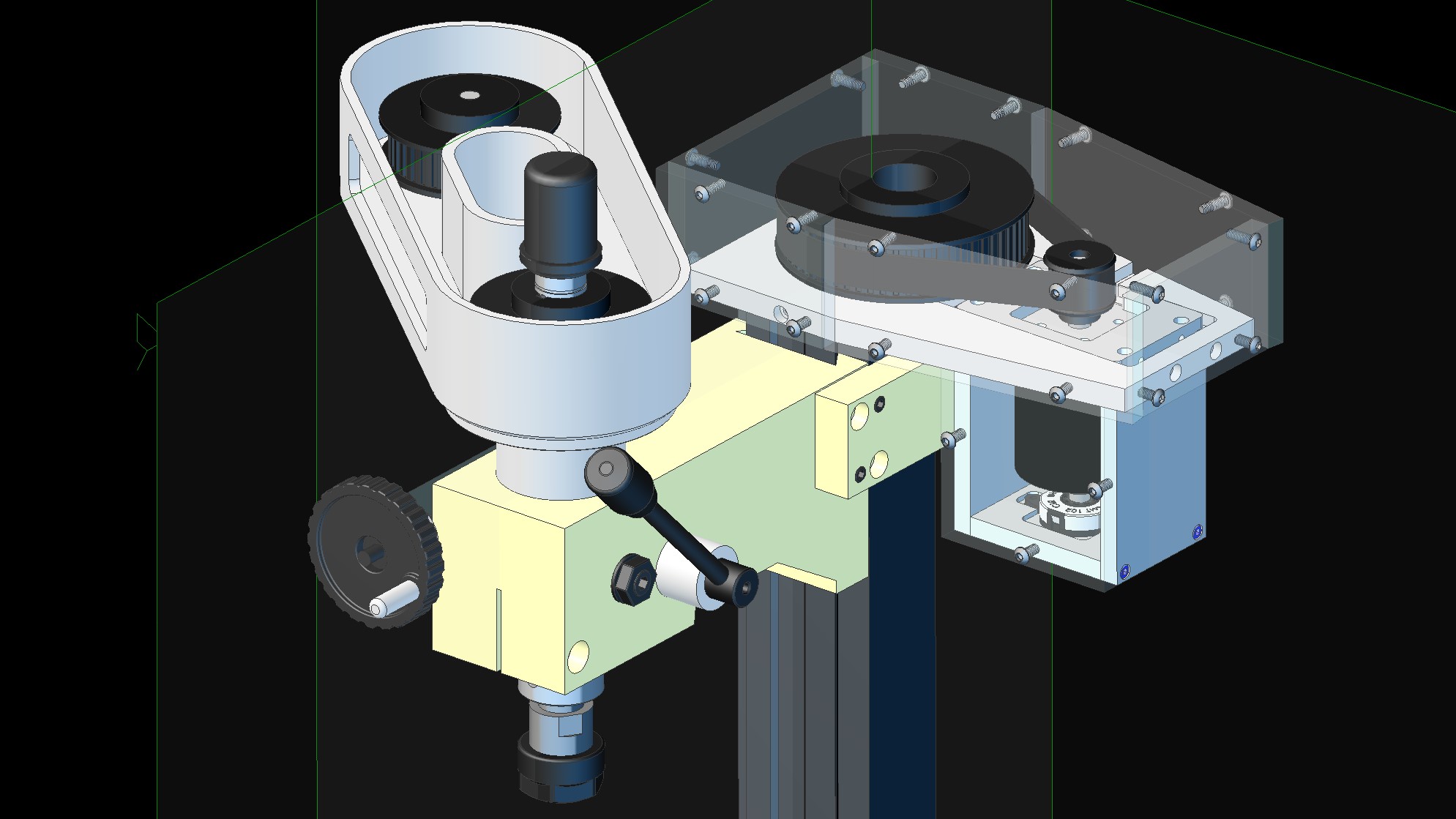
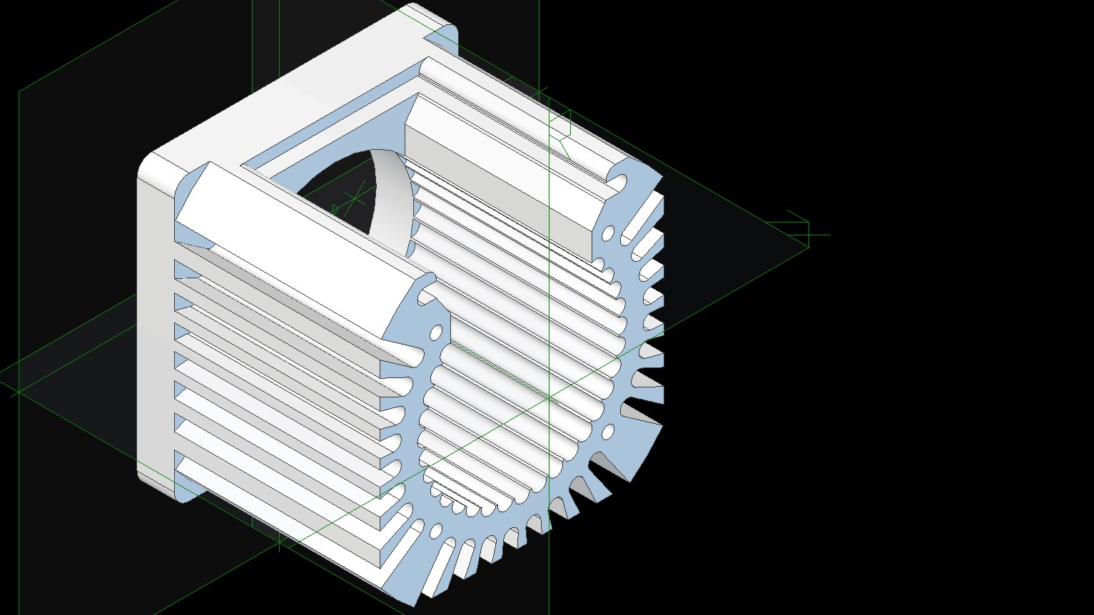
Image 2 does look burned out, although it just needs a clean up, I’ve stripped it right down to transfer it over to CAD and also to replace the bearings (the seals had broken down and it was getting noisy). I’ve since ordered 2 brand new high end, high load, deep groove bearings that can handle 20,000 RPM, so should be mad enough for the job.
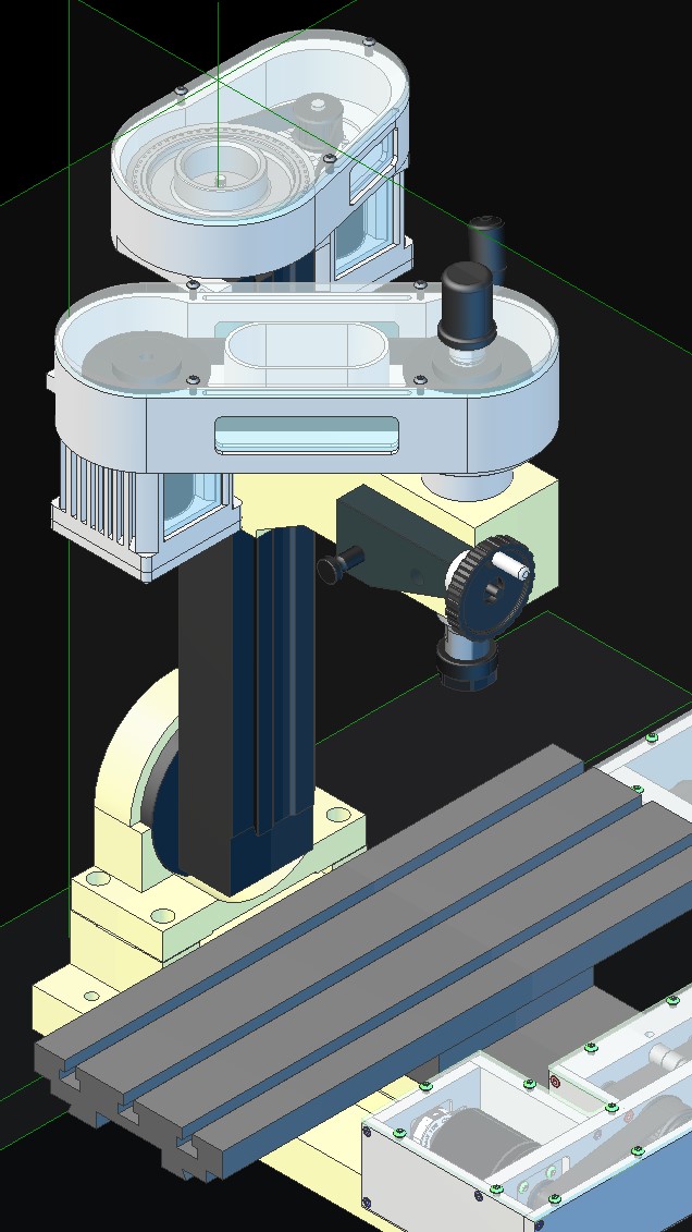
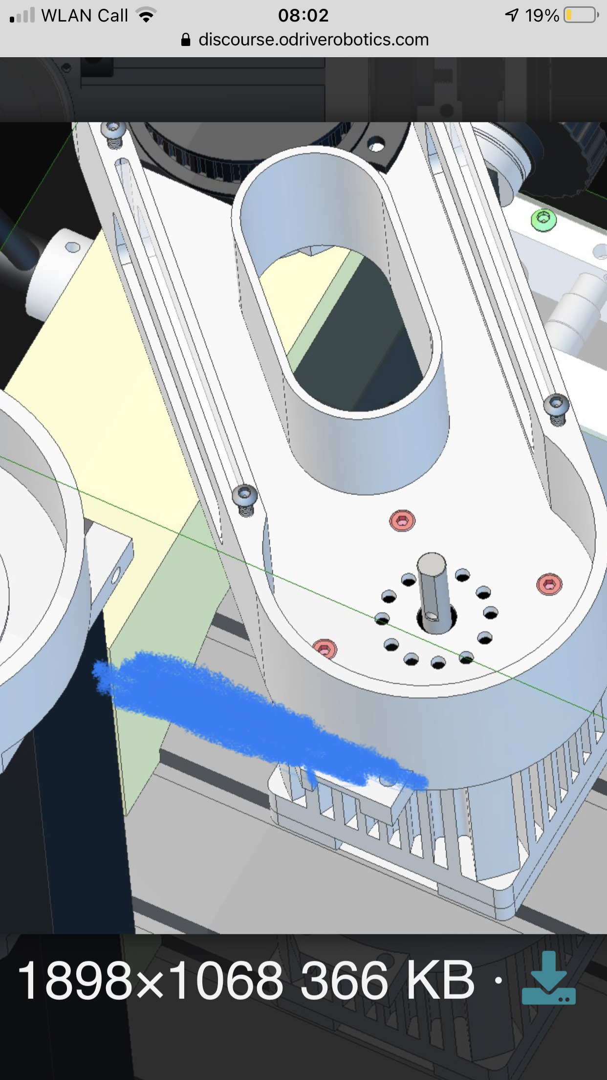
Image 3 is the start of putting everything on CAD, where I plan to do both the Z-Axis and spindle at the same time. Plus I need to do this so I can get orders in before UK Lockdown, hopefully.
Also, I won’t be putting a flywheel on as there will be plenty of torque in the ODrive motor and I fear hugely damaged parts/bits should the thing keep running following a crash… Hopefully not though (touch wood).
Ah, and I’m looking at adding a 70mm block between the base and the riser as there is 50mm of unused Z-Axis track, plus it would allow the Y-Axis to have around 15mm of extra travel.
Hmmm, Well… I’m really considering using the 56v ODrive as the main controllers in my MGF project, as @towen mentioned, it’s going to be difficult to get all the 24 motors running together, where with the ODrive it’s very tuneable and gives plenty of fast feedback, so I will be able to maintain torque output through current control (hopefully, we will see ). That means I will need 12 x 56v ODrives for the job and create a bespoke heatsink that spans across all MOSFETs with cooling. If I make these, it will be easy to produce a good number of them on my machine in one go
Part of using the 56v ODrive for the spindle motor is to see how controllable it is under velocity control to see if it’s a viable option for the MGF. I will then be able to stick a big ODrive sticker on the car (if all works well or maybe not if all blows up in an uncontrollable catastrophic failure .)
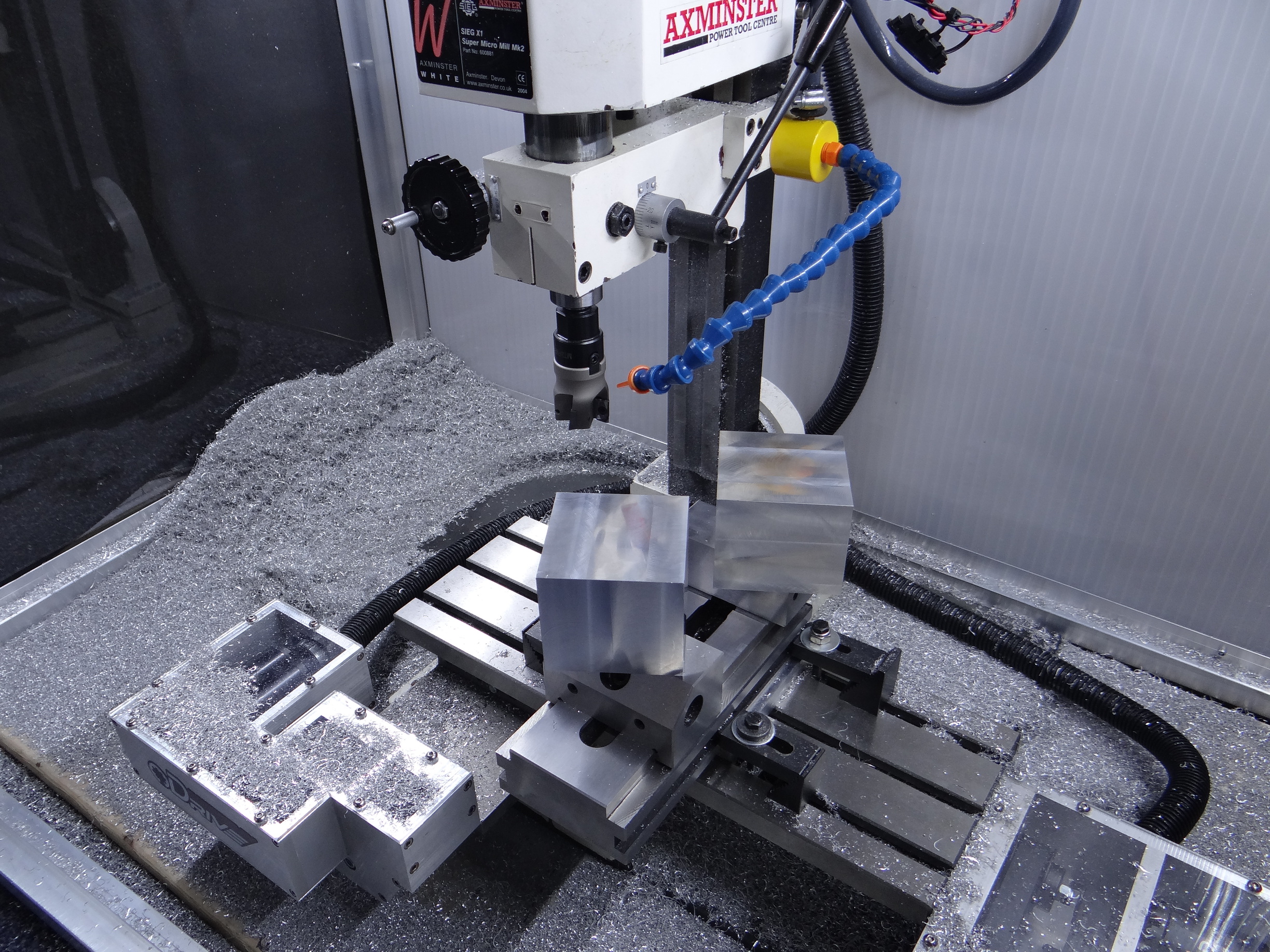
As for the mill so far, it’s back together with new bearings (although getting hot when running with a little pre-loading) and it has made it far quieter, everything is much tighter/ridgid, so should be able to cut much deeper and more confidently. as in the pictures below, I’m looking at machining out the spindle motor housing from 1 block of aluminium, so the machine needs to be up to the challenge.
Also, there will be a rotary encoder on the spindle motor for the machine tapping party trick.
Wow, these are powerful motors, they are a little expensive, I’m having to buy something every couple of months and do loads of research to reduce cost, that’s probably half my time at the moment. What machine would you put this on? You would need a monster controller on it too.
As for the construction advice though… I don’t like that they are two separate things. Can you combine the spindle motor? It might vibrate etc and pulling it to the other motor will make it nicer balanced I think?!
Thank you, I played with this design quite a lot, where I’m toying with the idea of milling the Z-Axis enclosure from one piece of aluminium, although this is expensive if something goes wrong.
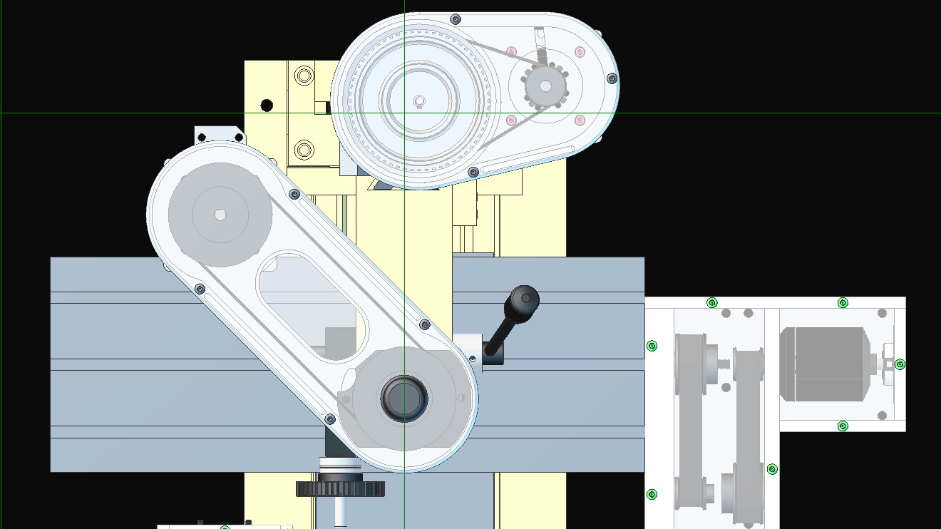
I’ve had to put the spindle motor on that side and far from the spindle as it would interfere with all the manual control elements, such as the manual quill lowering handle on one side and the fine control knob on the other, where I also wanted the motor underslung on both spindle motor and Z-Axis motor as the height is restricted in the cabinet I put together (I’m looking at raising the Z-Axis riser as there is around 50mm of unused travel at the bottom).
I’m also designing the spindle motor housing into a heatsink as this will probably get a little warm when running.
Can you see another option? Happy for suggestions as it’s still in the design phase.
Thx for your additional considerations. Makes more sense now indeed. Could you shorten the belts to perhaps get less of a vibrating bending on the spindle?
I think that making the housing of one piece of alu is counter productive. You don’t need the stiffness (belt is less stiff anyways) and would gain from the friction of bolted parts to lower the vibration with multi parts. Save the money although I think I’ll be so impressed with a movie of you, the mill and that one piece of alu ;-)!
No problem, I did toy with the idea of shorter 375mm belts (that actually arrived today) for the spindle making 87mm centre distances with 40mm pulleys, although this would mean the motor would sit above the belt housing.
I agree, the bolting option would definitely be the cheapest way to go, although chose this way for a few reasons, mainly for how it would look both machining the part out and once installed, plus I get to see how my new chip extraction pump holds up to pocket milling.
The single block of alu (40mm x 300 x 100) will cost around £32 for 5083 Grade (one of the strongest non-heat treatable alu materials) where it will only weigh around 860 grams. So with motor pulleys and housing should only come to 2.4kg, so not too much strain on the quill. I’ve purposefully put the centre feature in to increase rigidity though.
I think the main driver for design, as it’s on YouTube is the looks, although it’s a very capable machine now with all the mods.
I’ve been off work for some time and have not been able to do anything here either, so I’ve been sitting at my desk tinkering with the CAD parts for the Z-Axis and Spindle.
I am now at ver 3 of most of these parts, so hopefully I can start machining them out soon. The motor housings are fairly complicated and machined from one block in order to test out the machine.
Hopefully the motor housing will sink some of the motors heat (we shall see how much). There is an obvious air gap between the motor and housing, hence the internal feature to stir the air around. The motor will have some heat sink compound between the stator mount and belt housing (motor housing and belt housing also), so should dissipate some through that.
I will be adding a couple of features to the Arduino sketch too, with one monitoring the temperature of all motors, reducing the cutting speeds to maintain a safe temperature and the other having a live feeds and speeds control, so I can live dial the cutting speed on the fly. Both of these will use the interpolation between all motors, so the spindle motor will reduce as the feed speeds reduce. There will be a trim control also for spindle speed to feed speed. This will also allow me to test what the machine is capable of while cutting a feature.
One thing I might suggest is that the AMT102 is not really suitable for a spindle motor.
Two reasons:
1: It is incremental- any slippage due to vibration or missed pulse due to noise is going to bork your commutation
2: It is not a non-contact encoder. It will wear out over time at high speeds
I’d recommend either an absolute magnetic encoder or (shock, horror) Hall sensors.
Actually, I’d say that Hall sensors are ideal for a spindle motor, since it doesn’t really go below 30RPM or so.
You can probably find a much more powerful motor for cheap, with built-in Hall sensors, and perhaps a built-in heatsink so that you don’t have to machine your own.
Ah, I believed it to be a non-contact capacitive sensor.
That’s not too much drama though as the bottom of the motor housing is easy to amend and attach a different sensor, I was thinking of making a few of these with NEMA 23 standard fixings also.
This is one of the reasons for sticking with the AMT, as I want it to also have position control for Z-Axis to spindle interpolation for machine tapping. We shall see
Ah, where’s the fun in that , I’ve already got all the components and materials.
It is, sort of… But in practice it has a lot of sliding contact. Maybe when it wears down it will become a non-contact encoder…
You can get a “position” out of a Hall sensor, certainly for the purposes of using it as a reference for another axis. It’s just a low-resolution encoder. The pos_estimate will smooth out the steps for you.
Machine tapping does sound like a good reason to have a high-resolution encoder though. How slow does the spindle need to turn for that?
I believe the slower the better as when you approach the end of the hole you slow down and reverse in sync with the Z-Axis, so the higher resolution the better I believe.
I had a look at the AMT datasheet, but it doesn’t list life of the device. I could have missed it though.
I won’t need much more power than the small ODrive one, as I’m going from 150W brushed to 1800W brushless, although won’t be reaching that level anyhow. I don’t believe I could machine anything on this machine requiring any more than 1kW.
Hi @Quintin_Brand, good thought, although I need to use the quill on the Z-Axis where the spindle motor and belt drive housing lowers and raises with the quill.
The current motor and gears are also mounted in the same way, only not hanging to one side.
I decided to keep the quill operation as it is handy for quick manual drilling.
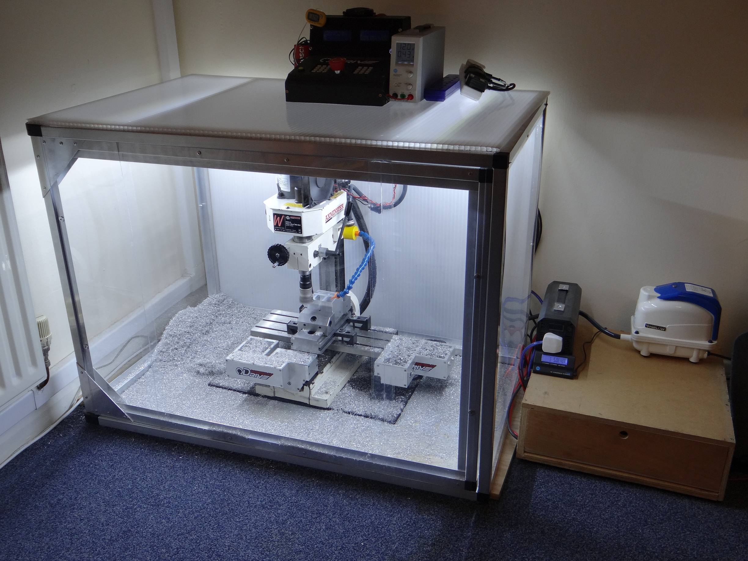
Well as you can see, this is becoming a great little workhorse (need a tidy up). The X and Y gibs are fairly tight now to improve accuracy, where the X and Y are now accurate to within 10µm, with backlash being well managed and lead screw wear being monitored (Increase wear for accuracy).
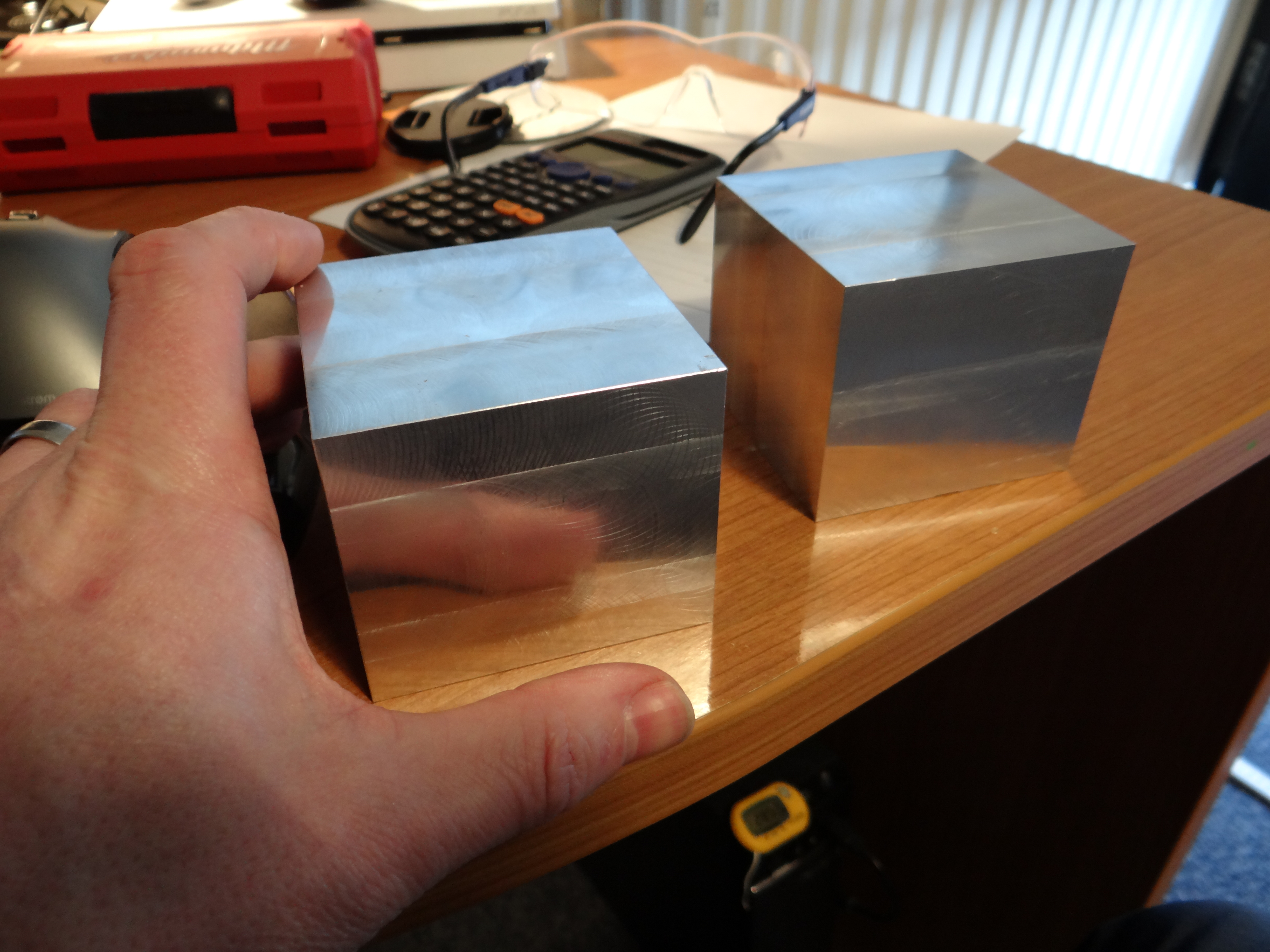
Both the blocks in the picture will become the motor surrounds/heatsinks, although these will take some time to make as they are fairly detailed and 5083 grade aluminium is harder to machine than I am used to. Still with the 40mm Shell Mill you get a pretty nice, almost mirror finish .
Hi Neil, great work; now stop teasing us and show a video in operation, I know I will definitely get a thrill while watching, I might even get a little sticky! “AJA”
Neil, you’ve produced something really special so kudos to you.
Thank you, here is a short(ish) video of chips flying from the 40mm cutter, although don’t want to push the plastic gears in the machine too much, they are only rated for 20mm dia milling max. Once the belt driven Brushless ODrive is on there it will unleash the beast from within
The video is unlisted so wont show up on YouTube search and there is no audio for the first part as my children were super noisy (louder than the mill ).


 .
.


 .
.
 “AJA”
“AJA”
