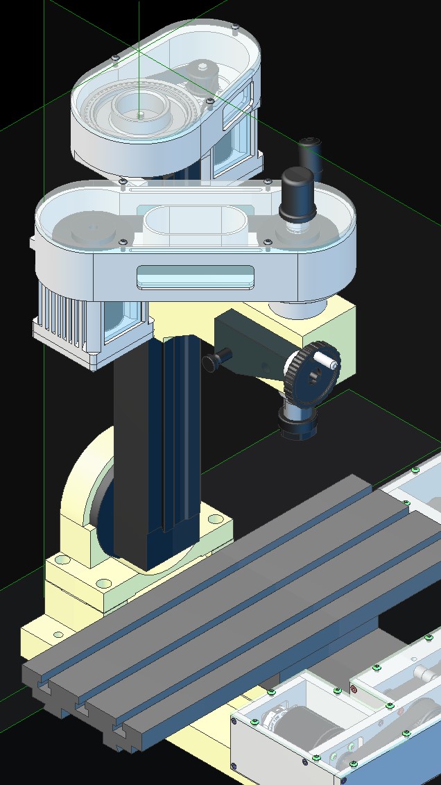
I’ve been off work for some time and have not been able to do anything here either, so I’ve been sitting at my desk tinkering with the CAD parts for the Z-Axis and Spindle.
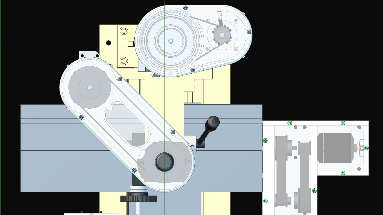
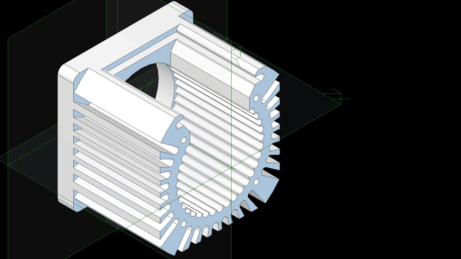
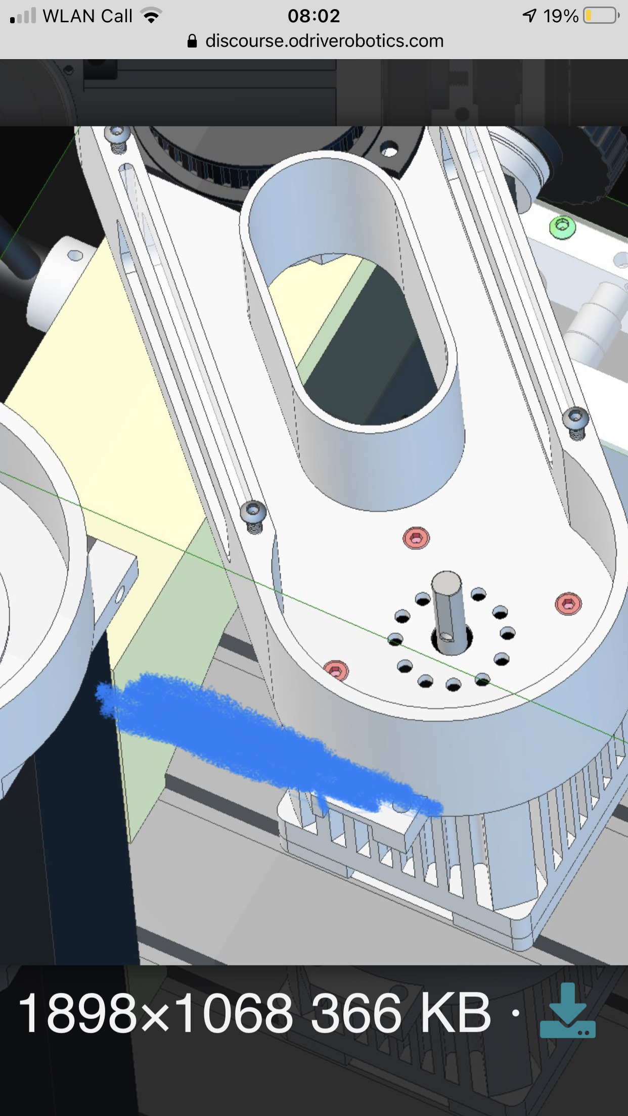
I am now at ver 3 of most of these parts, so hopefully I can start machining them out soon. The motor housings are fairly complicated and machined from one block in order to test out the machine.
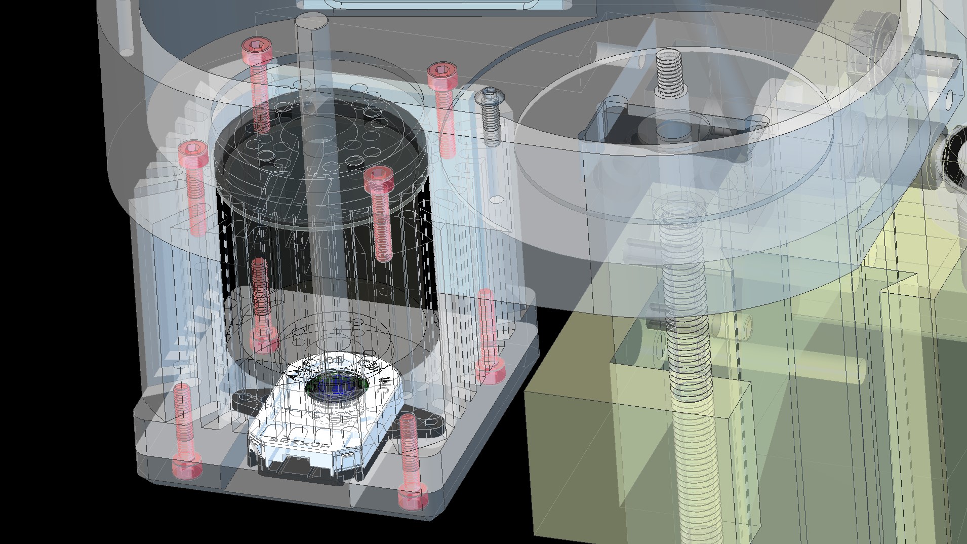
Hopefully the motor housing will sink some of the motors heat (we shall see how much). There is an obvious air gap between the motor and housing, hence the internal feature to stir the air around. The motor will have some heat sink compound between the stator mount and belt housing (motor housing and belt housing also), so should dissipate some through that.
I will be adding a couple of features to the Arduino sketch too, with one monitoring the temperature of all motors, reducing the cutting speeds to maintain a safe temperature and the other having a live feeds and speeds control, so I can live dial the cutting speed on the fly. Both of these will use the interpolation between all motors, so the spindle motor will reduce as the feed speeds reduce. There will be a trim control also for spindle speed to feed speed. This will also allow me to test what the machine is capable of while cutting a feature.
One thing I might suggest is that the AMT102 is not really suitable for a spindle motor.
Two reasons:
1: It is incremental- any slippage due to vibration or missed pulse due to noise is going to bork your commutation
2: It is not a non-contact encoder. It will wear out over time at high speeds
I’d recommend either an absolute magnetic encoder or (shock, horror) Hall sensors.
Actually, I’d say that Hall sensors are ideal for a spindle motor, since it doesn’t really go below 30RPM or so.
You can probably find a much more powerful motor for cheap, with built-in Hall sensors, and perhaps a built-in heatsink so that you don’t have to machine your own.
Ah, I believed it to be a non-contact capacitive sensor.
That’s not too much drama though as the bottom of the motor housing is easy to amend and attach a different sensor, I was thinking of making a few of these with NEMA 23 standard fixings also.
This is one of the reasons for sticking with the AMT, as I want it to also have position control for Z-Axis to spindle interpolation for machine tapping. We shall see
Ah, where’s the fun in that , I’ve already got all the components and materials.
It is, sort of… But in practice it has a lot of sliding contact. Maybe when it wears down it will become a non-contact encoder…
You can get a “position” out of a Hall sensor, certainly for the purposes of using it as a reference for another axis. It’s just a low-resolution encoder. The pos_estimate will smooth out the steps for you.
Machine tapping does sound like a good reason to have a high-resolution encoder though. How slow does the spindle need to turn for that?
I believe the slower the better as when you approach the end of the hole you slow down and reverse in sync with the Z-Axis, so the higher resolution the better I believe.
I had a look at the AMT datasheet, but it doesn’t list life of the device. I could have missed it though.
I won’t need much more power than the small ODrive one, as I’m going from 150W brushed to 1800W brushless, although won’t be reaching that level anyhow. I don’t believe I could machine anything on this machine requiring any more than 1kW.
Hi @Quintin_Brand, good thought, although I need to use the quill on the Z-Axis where the spindle motor and belt drive housing lowers and raises with the quill.
The current motor and gears are also mounted in the same way, only not hanging to one side.
I decided to keep the quill operation as it is handy for quick manual drilling.
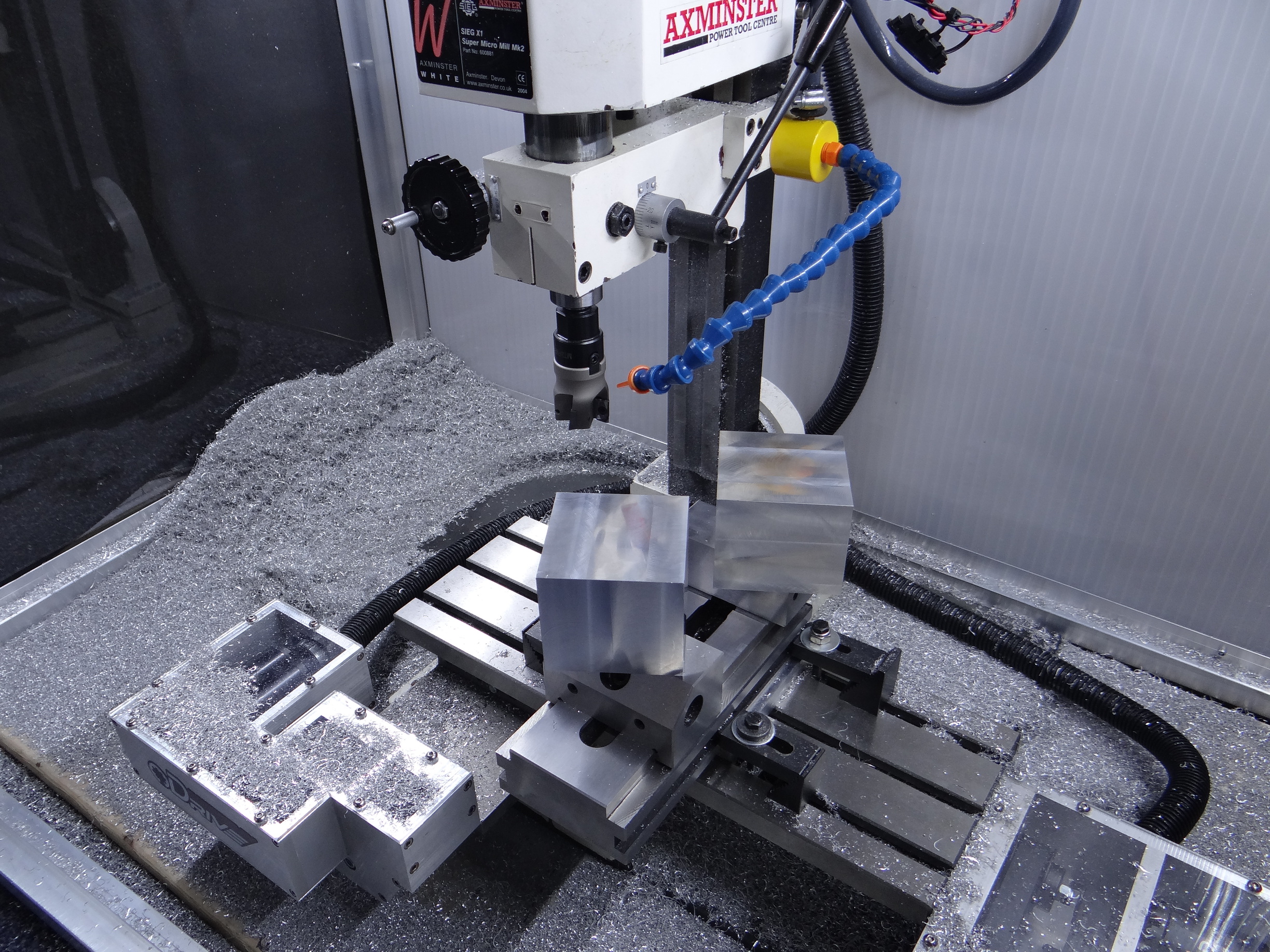
Well as you can see, this is becoming a great little workhorse (need a tidy up). The X and Y gibs are fairly tight now to improve accuracy, where the X and Y are now accurate to within 10µm, with backlash being well managed and lead screw wear being monitored (Increase wear for accuracy).
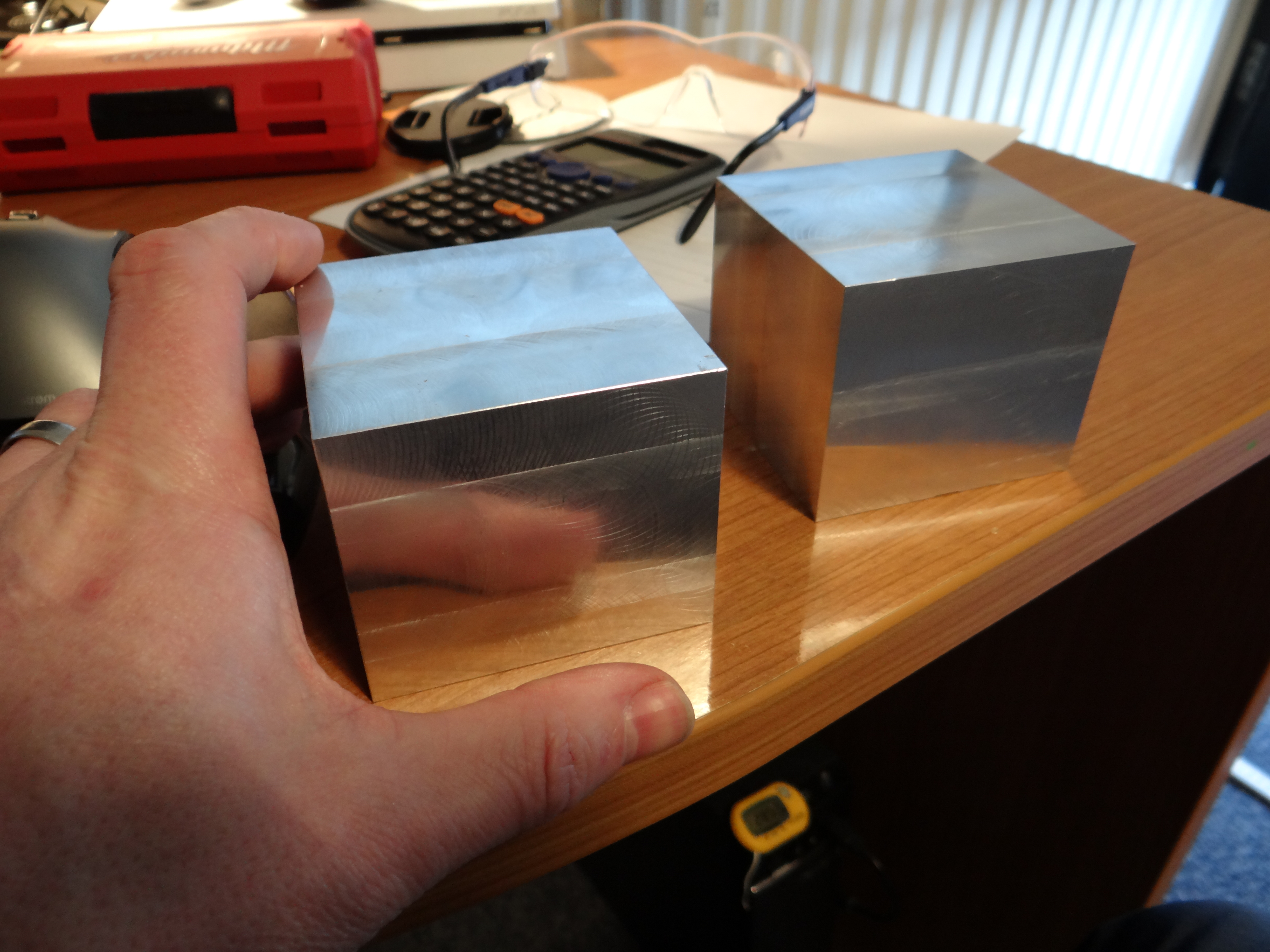
Both the blocks in the picture will become the motor surrounds/heatsinks, although these will take some time to make as they are fairly detailed and 5083 grade aluminium is harder to machine than I am used to. Still with the 40mm Shell Mill you get a pretty nice, almost mirror finish .
Hi Neil, great work; now stop teasing us and show a video in operation, I know I will definitely get a thrill while watching, I might even get a little sticky! “AJA”
Neil, you’ve produced something really special so kudos to you.
Thank you, here is a short(ish) video of chips flying from the 40mm cutter, although don’t want to push the plastic gears in the machine too much, they are only rated for 20mm dia milling max. Once the belt driven Brushless ODrive is on there it will unleash the beast from within
The video is unlisted so wont show up on YouTube search and there is no audio for the first part as my children were super noisy (louder than the mill ).
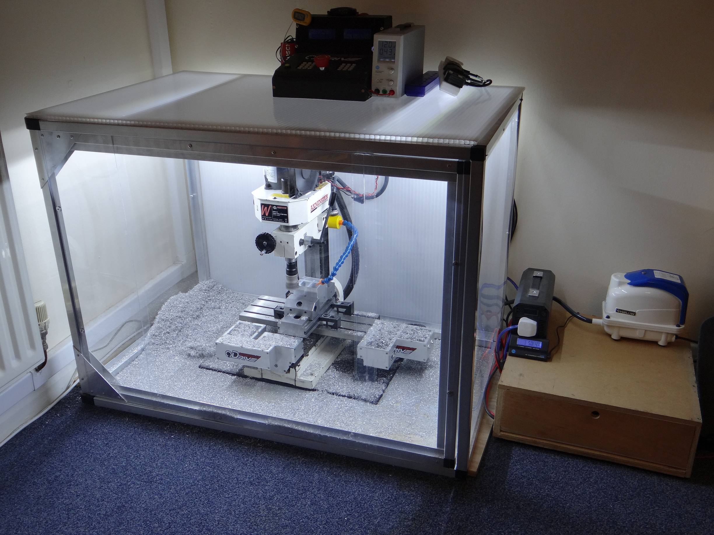
Very nice indeed, and I love the enclosure. Does it have a door?
It seems to keep most of the chips in, too! I bet your wife is “impressed” (i’m amazed that you haven’t been evicted to the shed! )
What’s the contraption next to the air pump? Is that your battery/inverter for the solar stuff?
Are you using that like a UPS? How long can it run off the battery?
I bet it will be a lot more efficient when you replace that induction motor too!
I’d be quite interested in buying some bits off you for my mill, when you have the time to make them!
Yeah, the full front is a door, making a video at the mo of how I made it, should be out in the next few weeks.
My wife and kids love it, think my wife is a secret engineer as she suggested it came into the lounge to prevent it rusting
The device is a 1000W pure sine wave inverter from Bestek (not Bestech, edited), it uses 1A itself so does increase the drain on the batteries. The spindle motor, cabinet lights and chip blower pulls around 170W in total, where the Z and X axis drive pulls around 1A each when moving at full chat. So all in all on the 75Ah battery from full charge lasts around 4 to 5 hours, although I’m only getting a low charge from the 50W solar panel with the UK sun, so running the spindle motor from the wall at the mo (although I am with a 100% renewable energy company for home energy, so still green).
I have used it as a UPS on the computer when video rendering during a power outage, plus it was running our fridge freezer also.
Think I may have been getting some noise on the encoder lines
I haven’t had this before, but I did change a few things recently that may have caused this to show up (increase noise).
I added 2 x 12v cooling fans to my spindle motor, this may be adding to the noise, although still happens when switched off.
Increased tension on the Gib strips to increase accuracy.
No.2 is where I believe the issue is coming from indirectly, where the motor is under slightly more load, therefore increasing the magnitude of the noise of the PWM signals and now interfering with the encoder.
I don’t yet have the motor cables twisted to cancel out the noise, nor do I have any shielding between the encoder cable and motor cables. In fact the encoder cable and motor cable are hugging each other for 0.5m up to the ODrive, (not ideal, but works ok with low current). The motors are only pulling around 750mA when moving and around 40 peak during acceleration from 0rpm, where the error only happened during a move.
I will be re-arranging my cabling, using cat-6 cable for the encoder and adding a twist to the motor cables, although just needed to get it reliably going again, so I did the following: -
Re-tuned both X and Y axis motors in accordance with the online the guide (due to the change in load). This reduced the frequency of the error, although did was not a direct fix.
Reduced the motor.config.current_lim on both motors to 10A. This did nothing to the error, I was just meaning to do this for a while and made sense to do it now. It may have reduced noise a little (not sure as have no access to spec anny).
Incrementally increased the velocity limit ratio under odrv0.axis0.controller.config.vel_limit_tolerance from 1.2 up to 2. I went through 1.2, 1.3, ect, and tested until it failed, where it was stable at around 1.8. So I set this to odrv0.axis0.controller.config.vel_limit_tolerance = 2
I have had no errors at all today with it running for the full day (touch wood). I still believe this to be a noise issue and will reduce this value again once I put some better noise control measures in place, especially when I attach the brushless spindle motor .
I hope this helps someone.
Happy ODriving,
Neil.
Edited: P.S. I have a 24v v3.6 board runing v0.4.11
Just thought you’d like to see my latest creation, purely machined out using my ODrive CNC machine with only manual Z-Axis movement every now and then… (I’m slowly making myself redundant )
I’ll be uploading a full video of the machine milling out all the parts at some point, hopefully in the next few weeks. The Z-Axis and spindle are coming along nicely too.


 .
.
 “AJA”
“AJA”


 (i’m amazed that you haven’t been evicted to the shed!
  )
)

