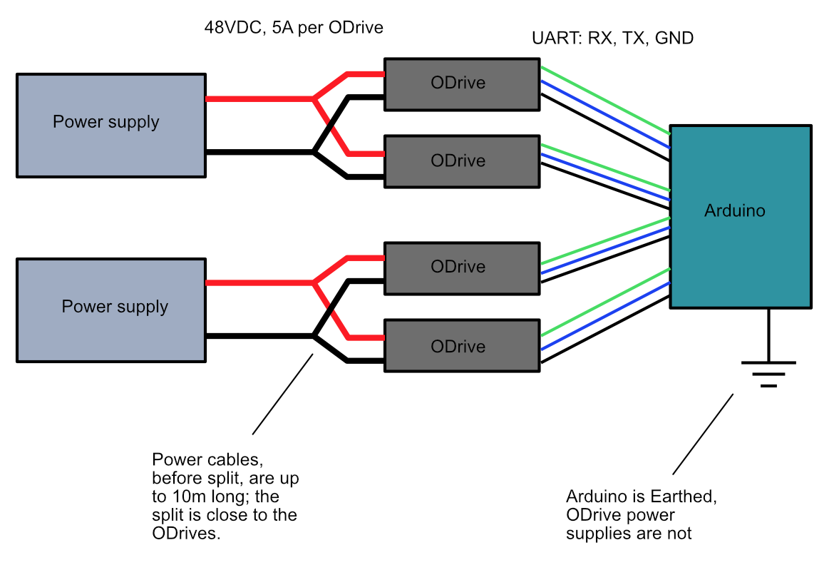
I have a system where 4 ODrives are powered by 2 power supplies, and the ODrives are controlled via UART by an Arduino. Each ODrive board is expected to consume a maximum of 5 amps total. The power cables leading to the ODrives will be very long, several meters, but all other wires are short. The power supplies for the ODrives do not have a connection between their V- and earth, but the Arduino does (it is connected to a computer by USB). Approximate diagram:
I have been running the system without any issues so far, but testing has not been with nearly full load yet, and the test setup uses cables that are not nearly as long as the final ones will be. So in thinking ahead, and mostly to avoid frying anything, I’m trying to understand the risks of a ground loop occurring. From what I can tell after reading about ground loops on here, these are the factors in this situation:
Since the ODrive power supplies are not earthed, there is not a risk of a ground loop that involves the power supplies themselves. Is this correct?
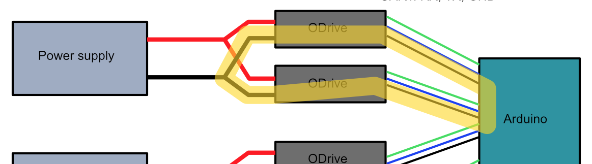
However, because of the split in the power lines, a loop such as this exists (highlighted in yellow):
But the physical circumference of this loop is not very large—I would approximate about 3 feet total. (The wires from the power supply are several meters long, but the split is close to the ODrives.)
The ground loops documentation implies that ODrives are at risk of creating a ground loop due to their high current consumption. Since in my case each ODrive is only expected to consume 5A, is that even in the order of magnitude where I should worry about it?
As a separate but related issue, be careful that the inductance of your long supply cables does not cause you an issue with interference / voltage ripple. I’d advise to twist the power supply wires to avoid DC_BUS_OVERVOLTAGE errors at high loads.
Remember that both of your supply wires have a voltage drop. At 5A, that could be as much as 1V, depending on the length and gauge of the supply wires. So the ODrive’s GND is actually raised by 0.5V or more above GND. And with a high inductance in the wires due to their length, it could spike to a lot more than that.
This means that your Arduino can potentially carry some current between two ODrives.
If one ODrive is at full load, and the other is at no load, there will be 0.5V (say) difference between the GND on each board. That will try to go via the Arduino, and it will also subtract from the 3.3V signalling voltage of the UART, causing communication glitches.
When you extend the power and UART cabling and increase the load, this could be a problem for you. Have you considered using CAN instead of UART? It is designed for this application specifically.
Also, I would be skeptical to rely on the fact that the PSUs are not earthed. Firstly if they have metal cases, they are probably MEANT to be earthed, and disconnecting the earth would present a hazard.
Secondly (assuming you actually meant to say “isolated” or “floating” when you say “not earthed”) they will still have a non-zero capacitance to ground. That means that high frequencies will still pass between them. Since ODrive works at 40kHz+ this could pose a problem with noise.
Yes to clarify, the power supplies have an earth terminal which is connected to the wall outlet’s earth, so the chassis is safe, but a multimeter shows no internal connection between that earth terminal and V-.
So would switching to CAN between the ODrive and the Arduino eliminate the aforementioned risks? I would assume the CAN bus would need the ground connection between the boards as well, but in that case the ground connection would be okay because of the differential nature of the signal? Any pros and cons to switching to CAN vs putting isolators on the serial lines? (aside from protocol specifics and extra hardware needed).
In addition to twisting the supply wires, would a bank of capacitors close to the ODrives be useful for this?
Yes exactly.
CAN is robust to a certain amount of common-mode voltage. That is, a raised ground voltage affecting both differential signals the same way.
Pros of CAN vs isolated UARTs:
It’s a lot cheaper - you just need one CAN controller for all four ODrives, since the comms bus is shared, and ODrive already has transcievers on board.
It’s more robust even than isolated UARTs, since the low-level protocol has packet retransmission and CRC built-in. If you lose some messages or they are corrupted, it will pose no problem.
You don’t necessarily need the Arduino - You can get a CAN controller for PC or Raspberry Pi and use it directly from Python
Cons:
It’s a different protocol, and you can’t (yet) use ODrivetool via CAN.
It is, however, extremely simple to use for control-related commands (but you will still want to use USB for configuration)
Potentially yes… The ODrive already has quite a lot of capacitance with a low ESR (equivalent series resistance), and large electrolytics tend to have a high ESR so they would be less effective at eliminating high frequency voltage ripple, but extra capacitance can’t really hurt.
Noob question : Is it the reason why sometimes we can see in some electronic stuff caracteristics that it is “optoisolated” ? Does it means that there is a component that translate the signal/data with something optical I guess, in place of the logic voltage?
Yes, ‘optoisolated’ means that there is a chip called an optical isolator involved - this is essentially an LED and photodiode inside the same package. It can transmit signals across an electrical insulator (a piece of glass) so there can be thousands of volts difference between the two sides, and no shared ground.
This is how we might switch mains voltages using a microcontroller, for example.
In RC hobby electronics such as ESCs, this means that the PWM input is actually going to the LED on the input side of the optoisolator, so the controller can be completely isolated from the main battery.
It is possible to get bi-directional optoisolators for transmitting data such as RS232, CAN and i2c, but these are expensive and complicated because they need to operate at high speeds, and sometimes need to be able to transmit signals in both directions on the same wire, so it’s no longer a simple LED/photodiode arrangement.
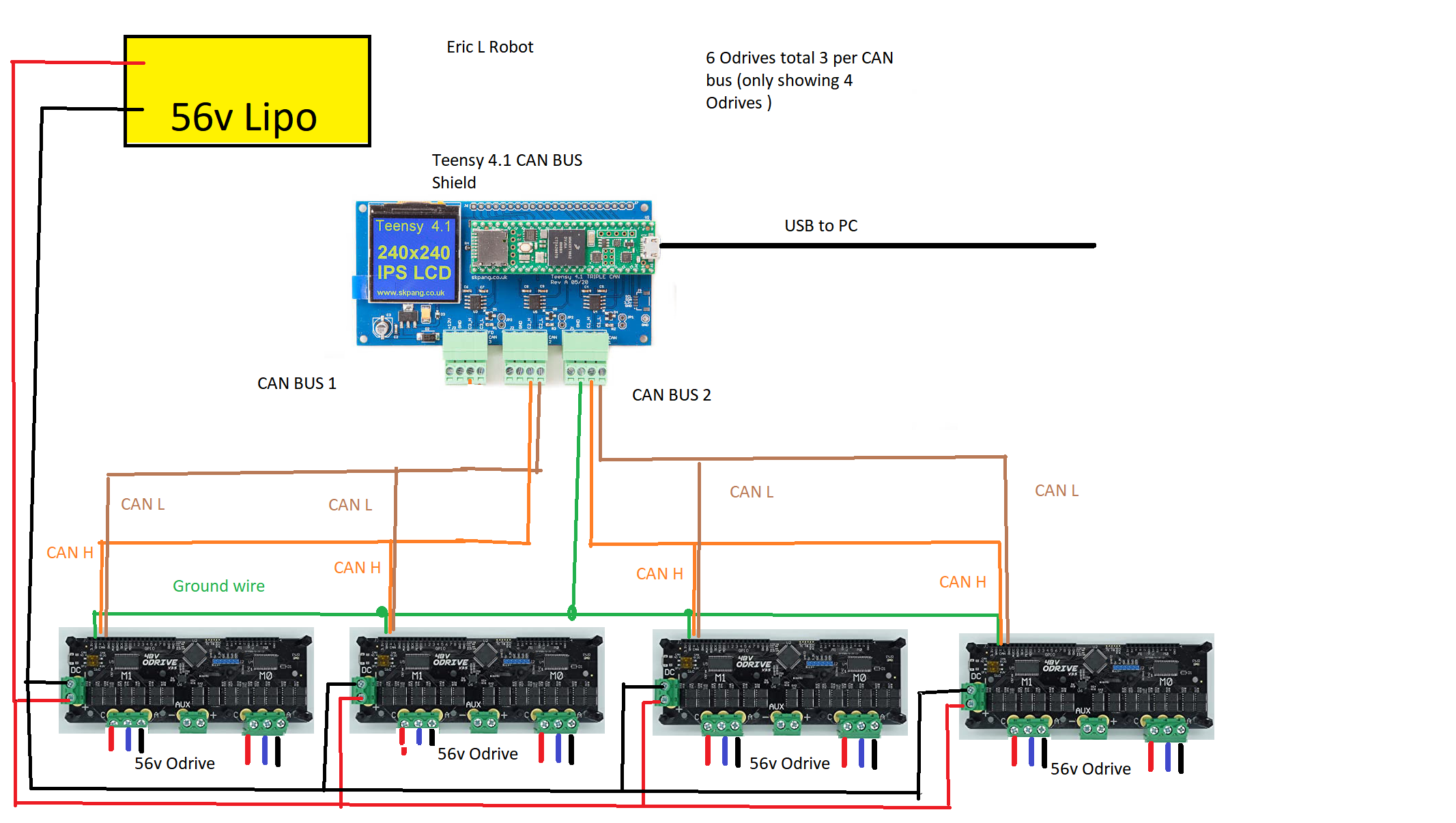
I think I’m having problems with ground loops too because my Odrives keep dying
Because I am using a CAN bus to communicate between the different ODrive’s I can’t use an Opto-Isolator because 0 is 2.5v and 1 is 5v on the High and 0v on the low wire. (I think that’s correct)
I could use a USB Opto-Isolator and then power the Teensy off the 5v coming from one of the Odrives but I’m not sure this is a good idea or if it would even solve my problem.
Currently, I am using a common ground like in the picture but in the past, I have not connected all the grounds together and I still had the same problem. Let me know what you think thanks
FYI this is what I’m working on (sorry the video is a little cringey)
I’m looking at these ISO776FDW for bi-directional Opto-Isolation and have 9 of them along with 9 breakout boards from This Post. They can handle CAN bus, RS232, RS485, etc upto 100Mbps and protect against ground loops.
Here is the PDF for the ISO776* family of chips. Take a look at Page 1, Para 3 (description) it mentions CAN bus.
These chips will most likely make their way onto ODrive V4 for this very reason.
In my case, I only have 2 wires for CAN Bus and it works without any isolation, i.e. I do not connect GND.
If you do connect GND, you should perhaps use a common-mode choke between the Arduino and the ODrives.
When you say your ODrives keep dieing, what do you mean? Do you mean permanently (with or without smoke) or just spurious comms dropouts?
Gah, yes, I didn’t even notice that till now! @itisieric 56V is an absolute maximum input voltage for the ODrive, not a “recommended voltage”! It will work perfectly fine with a lower voltage. But anything higher than 56V is almost guaranteed to cause damage.
From your video, it doesn’t look as if your Kv192 motors are spinning anywhere near the limit of 56 * 192 * 0.8 ~= 8600 rpm, so you could easily go down to 48V or even 24V.
If for some reason you need to run at that high voltage, then I would definitely recommend some inrush protection such as anti-spark connectors!
I should’ve clarified this earlier. I have had the same problem on 24v and on the full 56v. I mostly test in 24v and that is where I get most of the problems with the “Odrive dying”.
When I say “dying” I should have said that the Odrive USB refuses to show up on the PC and the Odrive will not respond, sometimes I can change it to DFU mode and re-flash the firmware and then it starts working again but sometimes that doesn’t work. I am only assuming it could be a possible ground loop. I’m going to try and add a temporary resistor in series when I first power it up for 2 seconds then bypass the resistor. Maybe that may help because the problem always happens on power up.
An anti-spark connector will do exactly this, and protects ODrive from inrush currents.
However, the usual symptom of inrush damage is smoke. I’d be surprised if it could be revived by DFU.
I suppose it’s possible that you connected the +24V before the GND. If anything else is connected to the battery GND when you do that, it would cause a surge through some device grounds.
XT90-S connectors solve this problem too, because the ground pin mates first.
@itisieric Did you get any resolution on this issue? We are having the exact same behavior of the ‘dying’ boards (that then require re-flash). For us, seems most common when we cut power in a load-state and then try to restart.
Hi, I now have a stop button on my microcontroller that when pressed it reads the encoders position and quickly send that set.position to the associated motor before it lowers the reset pin of the ODrive, essentially hitting the breaks and stopping the motors to prevent a rush of current to a powered off board. I believe this is a category 1 emergency stop, where a category 0 would be to just cut power. I think category 3 is holding motors in position with power still applied. My system is very quick at responding as it’s constantly checking the button state, although you could have it as an interrupt. Hope that helps.