I have the ODrive 3.6 48V version, running off a 36V battery; I am trying to make it so that a logic level signal will turn the power on and off to the board; in the process I blew a bunch of P-Channel MOSFETS because that initial spark the board has fried them even though they were rated for the current.
Plus I later just measured the ODrive when idle and it was only 30mA so I decided to just leave it on all the time, so I gave up on the MOSFET power board and decided just to use a master power switch.
This is the really weird part though, no matter what switch I use, it will turn on the ODrive for a brief instant and then the ODrive LED will flicker green on and off… I measured the current and it looks like the switch will turn it on the full 30mA and then a second later it drops to about 6mA… and I can’t figure out for the life of me why… if I bypass the switch and just use the power plug to the 36 V battery to plug turn it on, it works fine… it will even work with the switch as long as the switch was on when I plugged in the battery! There is always a spark when I connect the power though. So there must be something about that initial spark that is screwing up the switches… and I have tried different 20A switches of different types and brands
Please help! Any ideas? I have never seen this behavior in any type of circuit I have ever worked with; what switches are you using to turn this thing on and off? I don’t want to keep it plugged into the battery full time.
If you want to be able to remotely control turning power on or off you could wire up a relay that gets a signal to pull power, I believe that’s how the Stanford Doggo has a wireless E-Stop (check out their post for details).
If you want a physical button, you could use an antispark switch like this that uses MOSFETs to turn on/off the power.
You could make an antispark loop key switch with a few XT connectors like this
You could of course unplug power to the boards when you don’t want to use them.
Probably a few other ways that I’m not thinking of. Seeing sparks when first connecting a battery is normal, as the capacitors on the board are filling up.
I can’t find anything on the Doggo wireless E-Stop; I’ll keep looking; as for a relay, just wondering if it will have the same problem that the switches are having, huge spark that is somehow creating a resistance layer?
You’re welcome! Check out their electronics section in their first post:
“Gigavac P105 Mini-Tactor relay so we can kill the robot power using an offboard ESTOP switch. We also put our two, 1000mah 6s Tattu lipo batteries down there.”
What type of switch were you using that was briefly turning on the ODrives?
Some good suggestions here. I’ll suggest another method.
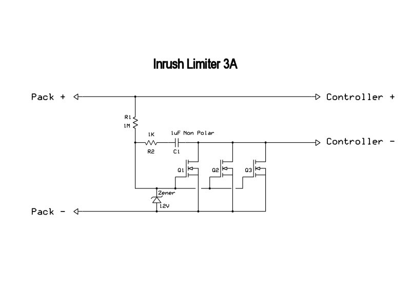
The MOSFETS are dying because the inrush current to fill the odrive capacitors is very large. If you use two MOSFETS, where one is connected to the circuit with a series resistor, you could first turn on the FET with the resistor, wait until the Odrive capacitors are filled, and then turn on the main (no resistor) FET.
Thanks… my switch was a 250V 20Amp toggle switch; very bizarre how it would turn on but only partially after a spark. I need a high side switch as I am using the USB port for data on the ODrive and I am afraid if I use a low side (ground on/off) for the ODrive, it may try and power up through the USB ground and short things out.
thank you tlalexander, yes I have been looking into this trying to figure out a circuit to use P-enh MOSFETS for high side control of the 36V; I found a nice low side N-enh MOSFET circuit but need sometihng to control the + side as I’m afraid otherwise the ODrive will use the GND from the connected USB port and try and power up using that
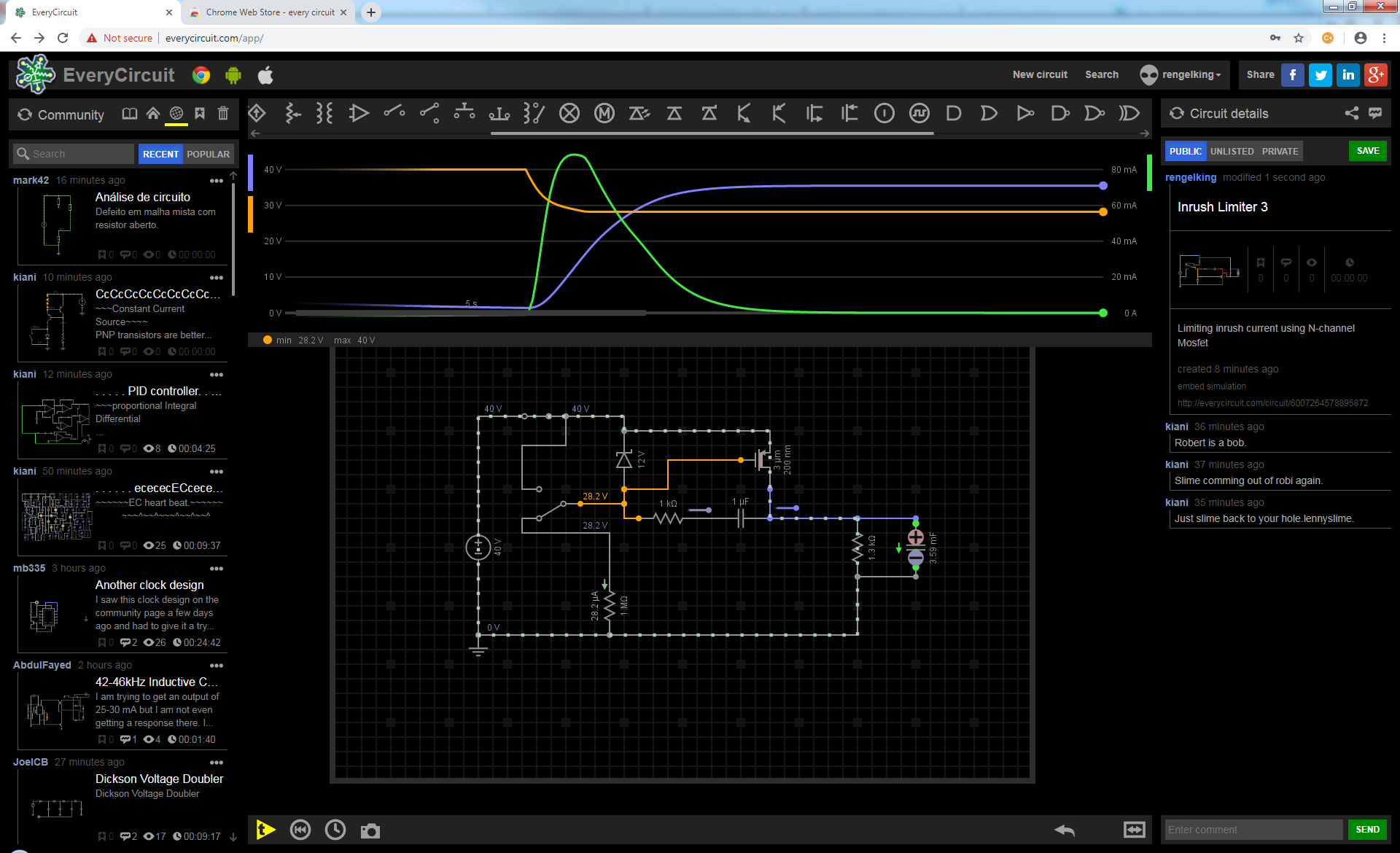
I reversed it and it seems to be working with a P-MOSFET from the high-side with a max spike of just over 100 mA; have to test breadboard it to see if it works:
Any improvements to this are welcome! Would be nice if something like this was built into the ODrive; this sparking is a big pain; that Gigavac switch is expensive, plus it has to be driven by 12V and it still gives a big power arc, and is only good for about 50,000 actuations at 50A and 24V.
Some of the other options of anti-spark cables are low-side controlled so they could result in a ground surge through the USB cable, so not a great option there either.
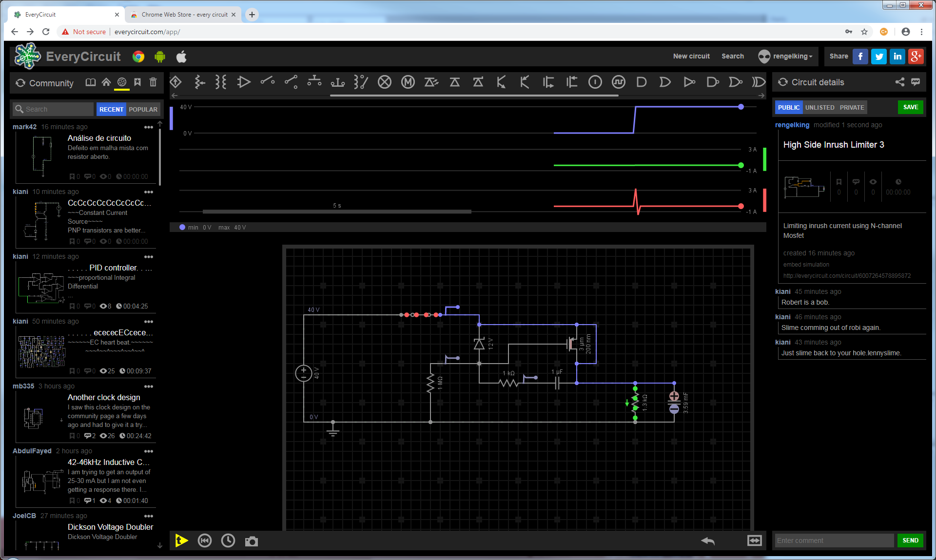
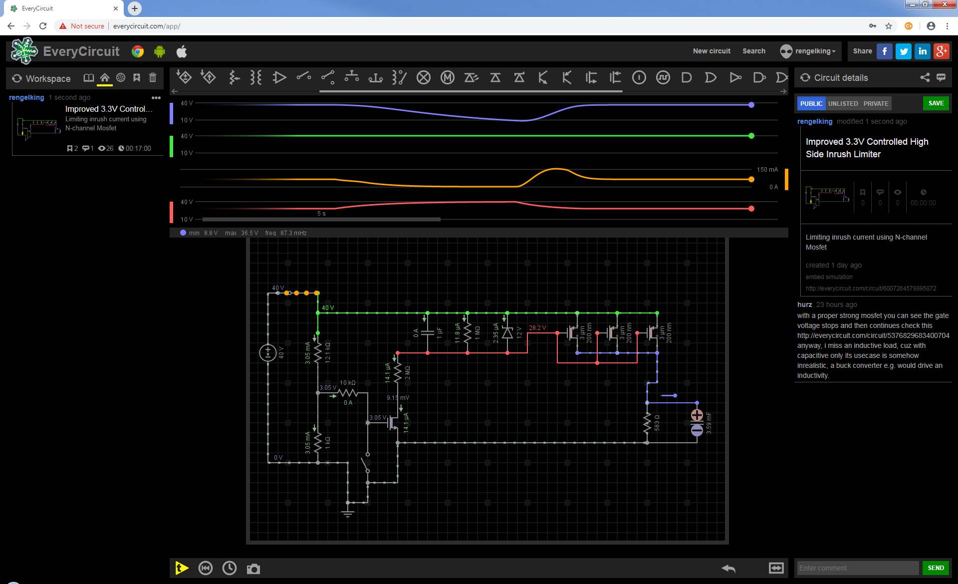
Thank you! Yes, I think that would still have the same startup current problem though; I ended up improving my startup circuit even more, it gives a nice slow charge rate up to 150mA when +40V first connected… it also allows a 3.3V logic level to turn the power on and off from a Raspberry Pi GPIO, and gives the same nice slow startup rate from the Pi turning the ODrive on and off:
The bottom left part can be driven from a Raspberry Pi output, I have it working in production, works great turning on and off the ODrive in between operating it through the USB serial on the Pi.
The P-Channel MOSFETs, I only needed 3 of those, not 4, they are FQP27P06 P-Channel MOSFET, 60V, 27A, TO-220,3-Pin (10 pack)
The N-Channel is 1 WeiMeet RFP30N06LE 30A 60V N-Channel Power Mosfet TO-220 ESD Rated for Arduino(10 Pieces)