Hi guys, I am using ODrive S1 and D6374 150KV motor and I am stuck at Unbalanced_phase_error during calibration stage. I have tried various things based on suggestions in various threads but none seem to work.
- I initially thought the connectors of motor phases are too big to go into controller, so I now have clips to connect to small 12 AWG wire to ensure proper connection
- I was initially used 48V 10Amps DC, but now also tried with 12V 30Amps DC and bumped up my max calibration current to 30Amps.
- I also played around with calibration voltage
None of these seem to work. Anything else that I can try to figure this out? I would appreciate any help. Thanks!
Hi! Is that a D6374 motor? Did you cut/strip/modify the phase wires? They have enamel insulation on the windings, which can be tricky to remove properly – that’s a common cause of this issue.
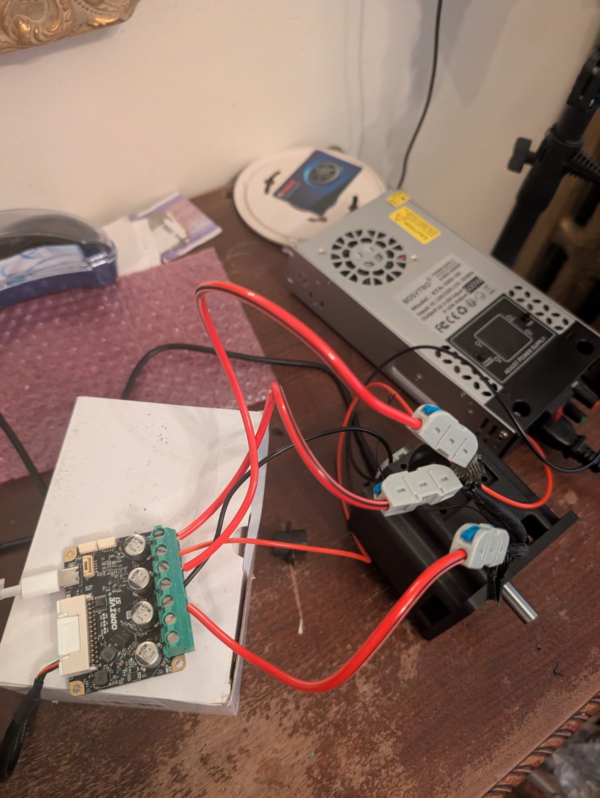
Initially I did not and I tried everything above and had the same issue. Then I also saw that the connectors of phase wires are too big to connect directly to O1 properly and maybe that’s why the connections are not set properly. So I have stripped the black insulation of phase wires and connected directly though clips shown in the picture.
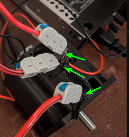
Would you mind showing exactly what the wires going into the clips look like? e.g. the ends of the three wires on this side
Ah - yeah, so that red stuff on the individual wire strands is enamel insulation. This is so each individual strand doesn’t short to the others in the motor stator.
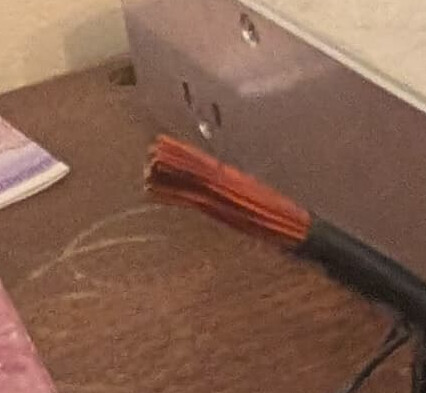
As a result, you’re only making contact to one or two strands, and the rest are remaining electrically insulated – the motor just won’t work like that.
You’ll have to get that off some way – here’s the option I use:
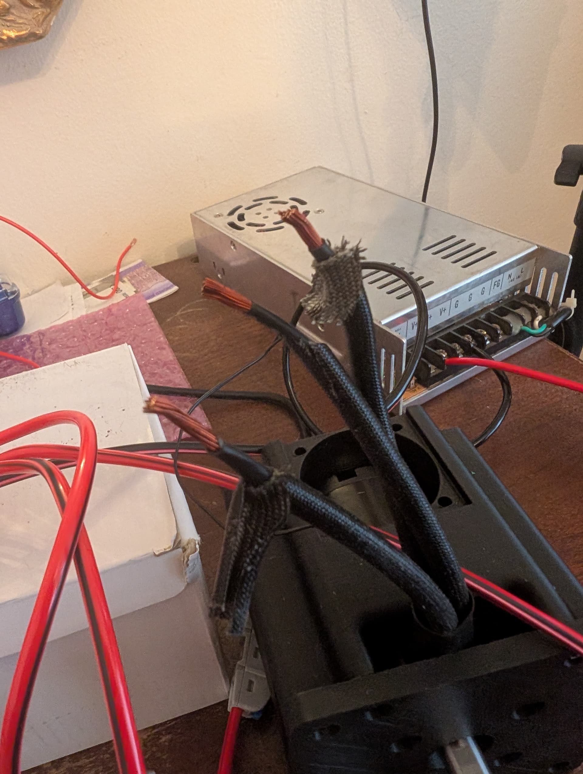
Get a solder pot, heated super hot, around 375-400°C. Drench the end of the windings in a really aggressive flux – something activated rosin is best, some common options for enamel stripping are Superior Flux #30 or Kester 1544 – no-clean fluxes don’t quite have the same aggressiveness, and may be totally ineffective for polyamide-imide enamel like this. Dip the ends into your solder pot, and hold for a good 5-10 seconds to burn off the enamel. Afterwards, verify there aren’t any dull/dark sections, and the wire is uniformly tinned. It may help to first hit the wires with a butane torch for a few seconds to burn the enamel, but you need to be careful not to anneal the copper. Make sure to thoroughly clean the flux residue either way, I’ll usually use anhydrous (99%) isopropyl alcohol, but there are some good hexane based flux removers out there (though I tend to avoid these, not something you want to be breathing too much of).
Okay, thanks for the help, I will try to do this. But I wonder I was having sameissues even when the phase wires had the default connectors and I decided to cut due to that. Do you know what could be the reason behind it?
If you were putting the bullet connectors directly into the S1, that could be it – they really need a proper mating adapter (which should’ve been supplied with the motor). Alternatively, it could’ve been a false positive, and just required bumping the calibration current a bit.
Oh okay, never got any mating adapter with the motor. Do you have any picture of how that adapter looks like? I might need more motors in future ,so I will make sure I get that too next time
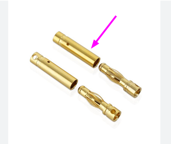
The D6374 is pre-terminated with bullet connectors:
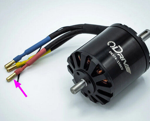
And it should have come with mating connectors in the box to solder to wire