Hi guys,
We have been driving the D6374 150 KV motor with an ODrive S1 successfully for a few months, and recently disassembled and reassembled the device. It now fails calibration after 1-2 seconds with only a slight movement and the error UNBALANCED_PHASES.
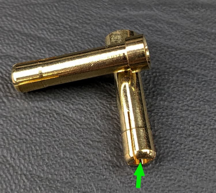
We measured the phase resistance with the motor disconnected, at the bullet connectors with a CC power supply and a multimeter. It works out to 54.4mΩ (red/blue), 84.8mΩ (blue/yellow) and 61.2mΩ (yellow/red). The nominal resistance is 39mΩ according to the ODrive motor spreadsheet. Unfortunately we didn’t measure the resistance on our motor prior to this.
During our testing, the system is powered with 24V, 5A current limit, from a benchtop DC supply. We have tried increasing calibration current and voltage in the motor config, which result in it drawing more power (from 0.5A up to 2-3A), but it still fails calibration immediately. We did not need to increase the default limits before.
When calibrating, the motor is connected to a 3:1 spur gear reduction but otherwise unloaded. We are using the onboard encoder, and the raw encoder values in the ODrive GUI show the encoder is reading correctly. The encoder is actually mounted on the output shaft, so we have configured the pole pairs as 21 (3 x 7pp motor), which was successful for calibration and operation before.
The motor doesn’t appear to be damaged and it was working properly in a test rig last week. We tried to disassemble it to inspect the windings, but it appears the set screw holding on the chassis is fastened with loctite.
Questions:
-
Are those phase resistances (54/85/61mΩ) sufficiently out of band to fail calibration?
-
Is there a way to widen the allowable difference? What would the impact on operations be?
-
Could severe bending of the motor cables cause a change like this in the phase resistance? One of our team members was a bit harsh on the wiring during reassembly. Is there any way to identify if that could be the issue, or fix it if it is?
-
The device this motor powers is a rotating unbalance, designed to generate vibrations. Could repeated use with an off-balance load result in resistance changes in the phases?
-
Any tips for further debugging or inspections we can do? Can we disassemble the D6374 motor to inspect it? Does the loctite in the set screw have a recommended temperature to allow disassembly?
Thanks,
Matt