Hello All,
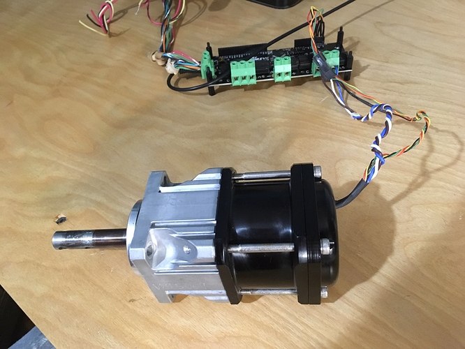
I’m new to all of this stuff. I have this nice motor with a 50:1 planetary gear box, but i don’t have any data sheet info on the motor itself. I’m trying to ID some initial setting for it to ease the learning curve.
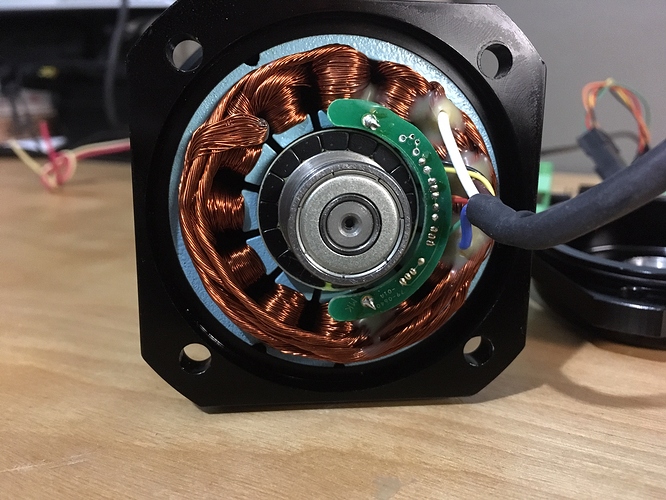
It has 3 hall effect sensors built in. For speed control? The wiring is similar to that of the Hooverboard write up, so I started with the Hoover Board setup page. I got it to move, barely.
In my Picture i count 16 permanent magnets and 12 coils. What would you suggest for pole pairs?
The Hooverboard write up also talks about motor resistance voltage, Current gain and band width.
How do i measure motor resistance and then use that to set my resistance voltage?
Should i even chance these values?
Thanks for the help
~Matt
The hall sensors can be used for two things:
- Determining which phases of the motor to energize.
- To determine the position of the rotor (and then divide by 50 to get output position).
You will need to know the number of pole pairs of the motor. Go here and look at “2. Set up Hardware Parameters” https://docs.odriverobotics.com/#hardware-requirements
You do not need to know the resistance and inductance of the motor. There is a calibration routing as part of starting up that will measure this. From the identified resistance and inductance, the system will calculate the current Kp and KI gains.
Because of your high gearing, you will not need to finely tune the current loop gains. If you are looking to do position and velocity control, even tuning these gains should be pretty easy.
2 Likes

