And I thought 3300uF was big!
Think if I add all my 63V caps together I can get close to that. Will give it a try tomorrow, thanks
When using the USB isolator, did you try disconnecting the ground link that you put between the ODrive and the Jetson?
It seems that mean-well has a lot of noise and may even be resonating with the odrive’s switching frequency (although adding caps should damp and shift that). Maybe with the frequencies involved, the ESR of the caps is too high.
The issue with the long cable is inductance and transmission line effects (although 2 metres should be fine for this tbh).
But again, if you are only holding position then yiu are not drawing hardly any current so any issues with wiring inductance should be minimal.
This is a really weird one tbh.
I suppose it’s possible that your odrive has faulty caps on the board… Can your multimeter measure the DC Bus capacitance? Also maybe measure the decoupling caps on the 5V and 3.3V pins on the board.
If you have a scope, see if you have any high frequency noise coupled onto these supply pins.
@Riewert
I soldered 4x 3300uF caps in parallel so total 13200uF and put as close to the oDrive connector as I could but made no difference unfortunately. Thanks for the suggestion though.
@towen
I hadn’t disconnected the ground link it but just did and still failed.
What confuses me is that my cheap low power PSU running off the battery had a much more coarse output than the Meanwell but that worked fine. So would make sense what you are saying about the specific out frequency of the Meanwell resonating with the oDrive’s.
My multimeter can’t measure capacitance unfortunately. However I have a few oDrives now so as the occasional sanity check I have been swapping out the one I’m testing. So seems fairly safe to say that the on board caps aren’t to blame.
I have a scope so will probe the 3V3 and 5V rails, plus the USB lines to see if I can find the offending noise.
Just noticed on schematic that the USB interface on U2 is powered by 3V3 instead of 5V. I guess this can’t help the SNR much?!
Thanks for your suggestions.
One other thing you can try, is disconnecting the feet from the body. There might be some capacitance between the motor and the frame.
Also, you really should be able to read out some errors, the odrives have a lot of failsafes against resetting. They throw errors if over- or undervoltages occur, and shut down the mosfets, preventing resets. Getting those error codes would really help debugging your issues.
It might also be the usb driver on your Jetson is fried or overly sensitive. Have you tried running the code on a seperate laptop instead of your jetson? Laptops might have beefier 5V rails that can absorb more spikes than your jetson (and help identify the weakest link).
So as I understand it, the ODrive is NOT resetting (it continues to maintain position and does not log any error) but ODriveTool (or whatever you are using to control it) is dropping out; i.e. Linux says in dmesg, usb device disconnected, and then odrivetool says Oh No odrv0 disappeared! - is that correct?
As I say I have had very similar USB issues with Roboclaw controllers on a Jetson, and since the things at that point had no watchdog feature, it was a serious problem. It was instantly solved with a USB isolator, (and they updated the firmware to add a watchdog after some pestering) but I am perplexed as to why @junglist is having such trouble. The 5V rail of the Jetson USB should not be a problem if using an isolator.
At this point, I would consider an alternative communication method. I have had a lot of success with CAN bus personally - once you have a transceiver set up and working in socketcan in Linux, it works perfectly
1 Like
@Riewert
towen has summarized correctly - oDrive does not reboot and there are no errors.
My laptop (and desktop) are more resilient to the issue than the Jetson so I have monitored for errors with that.
@towen
Correct.
Think I have just proved the issue is related to my steering motor specifically:
It only just occurred to me this morning that I should try the same test with my hub motor, which worked fine, no USB issue, even without using USB isolator.
I swapped the axis around that each motor was using, recalibrated and repeated test - the issue follows the steering motor.
I replicated the above on a separate assembly - so different oDrive and different steering motor.
With the hub motor holding position, I can force it as hard as I can to make it fight me, and this still would not create the issue.
So I guess this rules out my PSU. The hub motor is rated to 500W while the steering motor is 440W.
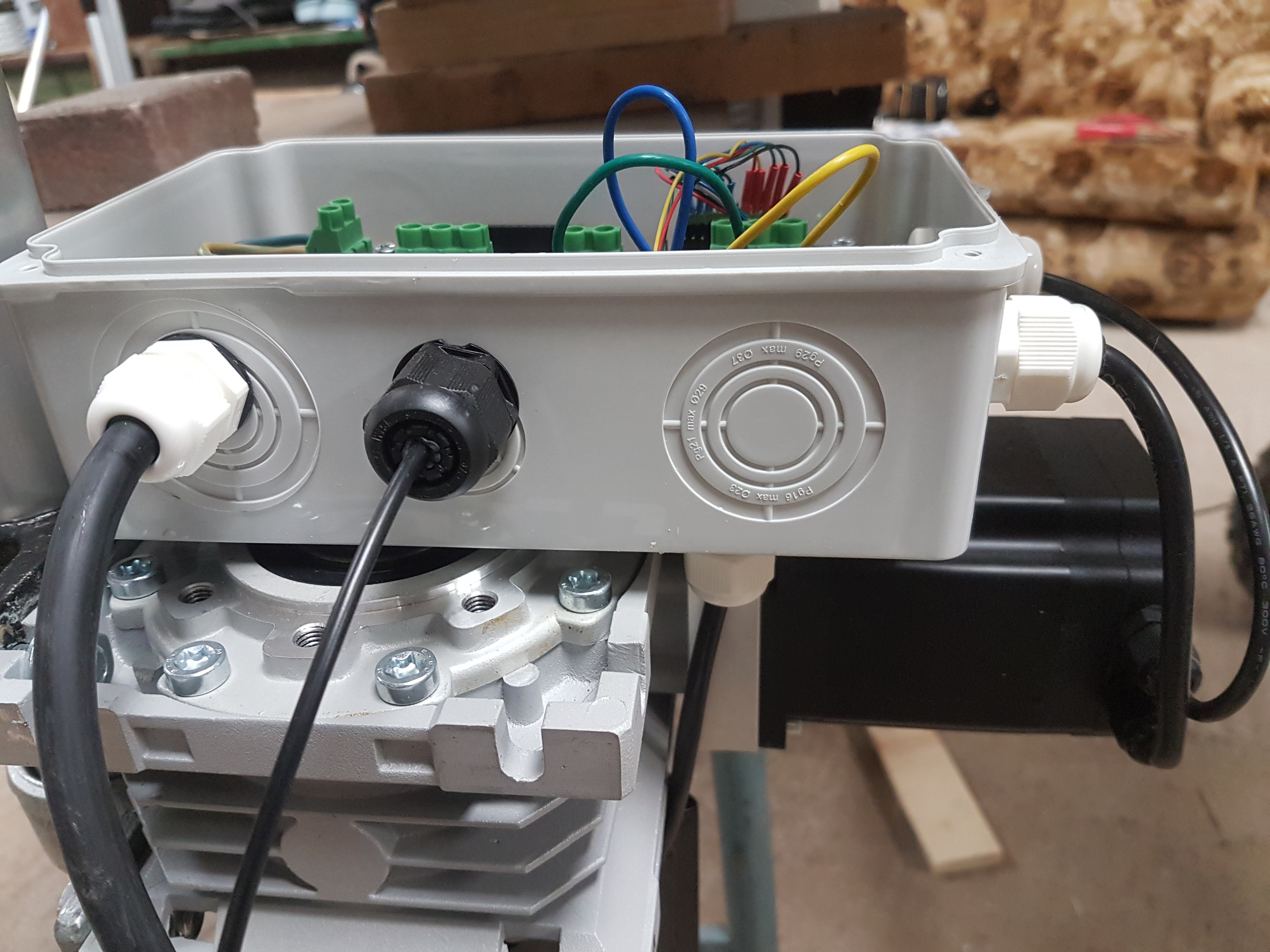
The steering motor is physically right next to the oDrive. Photo below.
I thought that the fact that powering from the battery test worked fine proved that this close proximity was not an issue. Unfortunately the wires on the steering motor are so short that I can’t move much further away without soldering extensions on it.
Perhaps I should have put the oDrive in a metal box…
I will keep trying to resolve USB for now but that failing that will move to CAN.
Can you show a picture of the inside, specifically of the mounting screws for the ODrive and the junctionbox? Maybe metal screws are allowing energy from your steering motor to penetrate your junctionbox.
Not so much the screws letting energy in by penetrating the plastic, but more like the plastic itself being completely transparent to EMI and near field magnetic interference from the motor.
USB is wired as a differential pair so it should be immune to near-field magnetics, unless the tracks on the PCB take different routes or have different lengths
You could try putting a steel or iron plate between the motor and the plastic box?
Finally got chance to work on this today. Seem to have gone full circle again and have seen the problem occur when just using the hub motor.
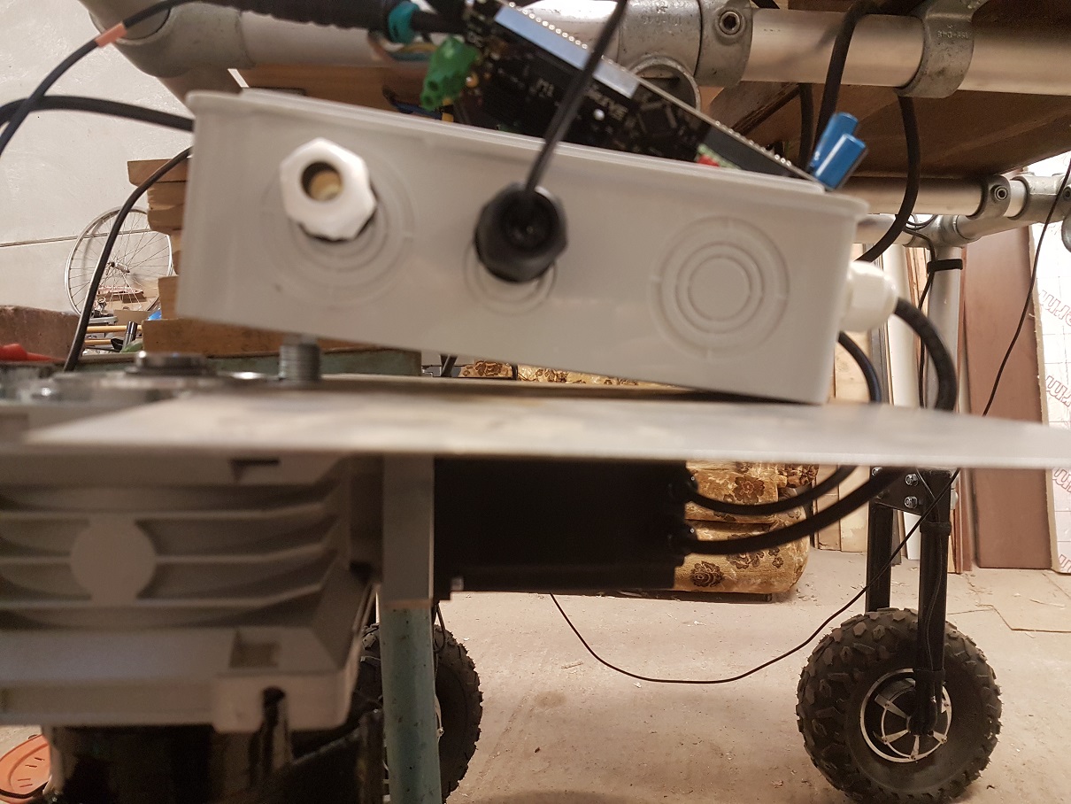
I bolted a 1.2mm thick steel sheet to the gearbox to try shield the oDrive as suggested. I tested it was grounded by the rest of the frame, which is connected to 0V (of PSU and Jetson) and mains earth. Picture below.
Unfortunately this hasn’t made any difference. Tried it with USB isolator and without.
I started probing for noise and found a 40uS waveform across C29 (5V Reg output) only when in AXIS_STATE_CLOSED_LOOP_CONTROL.
So I added a lot of extra decoupling which did attenuate it but did not get of it completely. Problem persists.
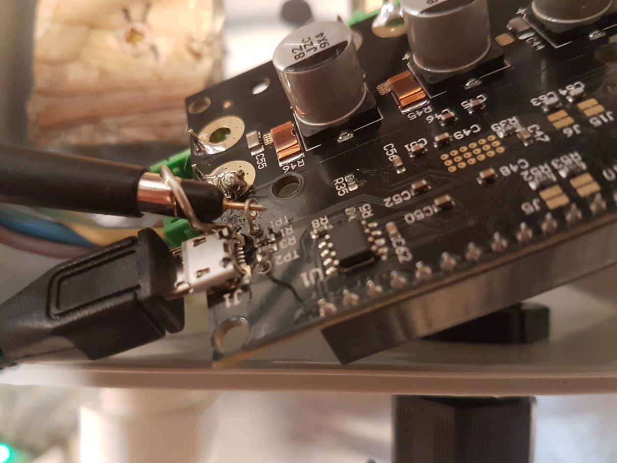
I probed TP1 and TP2 (USB_DM and DP) with an as short an earth lead as possible (see picture). I can see noise here and only when it fails. 20uS waveform at ~1V pk-pk with 2V spikes.
The noise waveform is not identical on DM and DP. The PCB traces do change their distance from each other and no effort appears to have been made to separate them from other traces. I have no idea how critical this is for USB.
After seeing the noise on the USB signal for the steering motor, I wanted to see it for the hub motor too. There is noise there but it is not as high amplitude, it did cause the USB to drop offline though a couple of times, which I have seen before intermittently throughout the project but had put down to the bad grounding issue. So seems the problem here is not just related to the steering motor.
I will put pictures below of the noise I am seeing on the USB_DM. If it’s not too much effort - would either of you able to probe it with a largish motor 400-500W to see if you see any noise?
This 40uS and 20uS noise is not present on the 48V into the oDrive.

Ok, so you have the probe on one of the USB data wires.
It’s possible that the signal you are looking at is normal USB communication. The AC coupling on your scope might be tricking you into thinking that it’s not a digital signal…?
The USB wires are differential so to see the actual data without noise over the top you would need to subtract one from the other. I guess that’s not a storage oscilloscope though, so you might not be able to do that…
You say you see the noise on the probe ONLY during the failure condition.?
Does that mean the noise starts immediately as soon as the USB drops out, and continues until you reset the drive?
If so, I wonder if it could be suffering from interrupt overload or something like that, e.g. some GPIO pin configured as an interrupt is picking up noise and spamming the microcontroller with interrupts - this could be starving the low-priority tasks i.e. USB.
20uS would equate to 50kHz. I think the PWM frequency is 25kHz, so you may be seeing spikes at both the rising and falling edges of the PWM cycle.
Just to be sure, you did get your ODrives from the shop on this site, not from Amazon/eBay/Aliexpress/BangGood?  There are a lot of very dodgy-looking clones appearing.
I have a fairly big motor I can try it on - I have a scrapped Turnigy Rotomax 50cc that I picked up to play about with. I also have a Jetson TX2, so can try that too.
I’ll let you know how I get on.
That would be amazing cheers 
Any sort of confirmation that it is definitely my setup or not would be really helpful.
oDrive is authentic from official shop.
I’ve uploaded a video of the noise below, think it will answer most of your questions.
I appreciate what you are saying about me probing a differential signal as singe ended. My scope is very basic… However surely even a diff pair will struggle with to cope with 2V spikes on a 3v3 signal, especially when the noise is not quite identical on the 2 traces.
I use generally AC coupling when hunting for noise so don’t have to keep moving the Y offset about when I zoom in.
At the start of the video the motor is in IDLE. I then hit enter in odrivetool @ 2 seconds:
odrv0.axis0.requested_state = AXIS_STATE_CLOSED_LOOP_CONTROL
The noise starts immediately and the Jetson drops of a split second later. Sometimes the Jetson will hang on for longer.
So the waveform in my previous post was taken by getting it into this state, then physically unplugging the USB from the Jetson, leaving only the noise waveform. Noise then continues until I reset the oDrive.
Interesting thought on the GPIO, I’ll have a dig into what the default settings are.
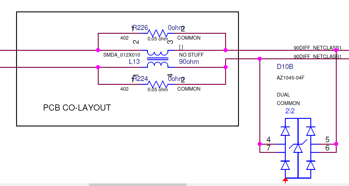
I looked at the Jetson TX2 carrier board schematic and found that they have pads for common mode chokes which are currently populated with 0R resistors. Maybe this is why it is easily upset?
Will probe the output of the USB isolator as surely this should reject any common mode noise too.
The issue just suddenly stopped. I could not make it fail and the noise on the USB lines was gone.
It was coincidentally just after I had disabled the UART, but enabling it again did not make it fail.
So I erased the oDrive and recalibrated - issue has come back along with the noise but bears no relation to the UART setting.
So now while probing the USB, I am controlling the drive with a laptop which does not drop offline (mostly) when the noise is present.
I can see the noise start when entering AXIS_STATE_CLOSED_LOOP_CONTROL, but when the motor is in motion the noise isn’t there.
When it stops in some positions it is present but in others it is not. When the noise is not present, if I reboot the oDrive then the noise comes back again when entering AXIS_STATE_CLOSED_LOOP_CONTROL.
So seems it is literally just the motor holding position that is the issue here.
The gearbox I am using cannot be back driven so I don’t need it to hold at all.
I am presuming there is some setting that will stop the oDrive from trying so hard to hold position but have not found it so far.
Settings tried:
pos_gain, vel_gain, vel_integrator_gain - all set to 0
current_control_bandwidth
disabling encoder interpolation
enabling vel_ramp - wouldn’t stay enabled on save then reboot
We’ve had issues where the motor casing can couple a lot of noise to the ODrive if you’ve grounded it, and various other issues. You can test for that, or you can try braiding the the motor wires and adding an inductive choke (I think @madcowswe has a picture of his setup he may be able to share as a reference)
@Wetmelon
Thanks for the suggestions. I think understand the braiding part but not where to place the choke.
Disconnecting incoming mains earth from the frame (which is connected to the metal motor casing) made the noise worse.
Disconnecting 0V of PSU from the metal frame didn’t look to make much difference.
Then after all this time I noticed that if I unplugged the USB cable from the oDrive that the noise disappeared completely!
I tested with 3 different USB cables, one of them was shielded but they all showed the noise.
So with a USB cable plugged only into the oDrive (so no host computer) and moving the USB cable around, I saw the noise got worse the closer to the metal frame it got.
I then repeated this test on the bench away from metal frame.
Proximity of USB cable to the 3 motor phase wires or the oDrive itself made no difference.
But the closer I moved the USB cable to the metal gearbox or motor, the worse the noise got.
So seems I need to not have any metal connection to the motor/gearbox housing. But that isn’t really possible when the entire robot frame is made from metal…
Think I shall try using CAN (as towen suggested) to see if it less sensitive to the noise.
Before all the above - I spent a few hours trying different config settings and re-calibrating to see if I could tame the holding force of the motor. Nothing has made any difference so far.
The noise is only bad enough to be an issue (for the Jetson) when the average motor current is at 0Amps.
Video summary:
Scope shows USB_DM.
Entered CLOSED_LOOP_CONTROL - noise appears.
Closed odrivetool - you can see the noise by itself.
Opened UI_odrivetool - you can see average current is 0A and pulses to +/-300mA. Noise is at it’s worst here.
Moved position, noise decreases further from 0A average you get.
Set current control mode to put average back to 0A. Noise bad again.
Video done after re-calibrating with - odrv0.axis0.motor.config.current_control_bandwidth = 50
In [6]: odrv0.axis0.motor.current_control
Out[6]:
p_gain = 0.009802485816180706 (float)
i_gain = 5.2717108726501465 (float)
v_current_control_integral_d = 0.0 (float)
v_current_control_integral_q = 0.0 (float)
Ibus = 0.0 (float)
final_v_alpha = 0.0 (float)
final_v_beta = 0.0 (float)
Iq_setpoint = 0.0 (float)
Iq_measured = 0.0 (float)
Id_measured = 0.0 (float)
I_measured_report_filter_k = 1.0 (float)
max_allowed_current = 30.375 (float)
overcurrent_trip_level = 33.75 (float)
Good to see you found some sort of relationship between the robot and the noise. CAN is a very robust protocol, I suspect it’ll be much more reliable for you.
Huh. Why is that so low? You usually want it up in the 1000 range
Fixed it! 
@towen & @Riewert were right from the start - was a grounding issue.
I had 48V and 0V connected to the oDrive via a 2m cable. Then near my PSU I had connected 0V to the Jetson and to metal frame.
So I replaced the 2m 0V connection in to the oDrive with a connection to the metal frame directly next to the oDrive. So the frame is now the 0V conductor for the oDrive, rather than the frame just being connected back at the PSU end. All noise has disappeared!
Thanks for your help.
Sorry if this is what you were saying to do all along, I had obviously missed that point…
@Wetmelon - I decreased it when trying to rule out config settings causing the noise. The hoverboard guide put it at 100, so had assumed for a larger motor I should decrease it even further. I shall increase it a lot then.
3 Likes