Using odrive to "stabilize" a large load?

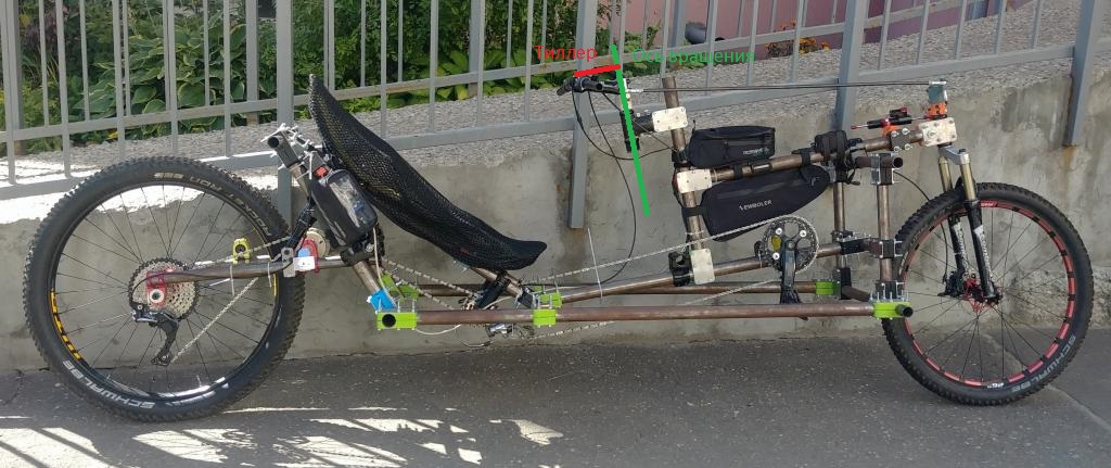
Basically, I have a recumbent bike and a particular problem of road imperfections beating my bad back and causing nasty cramps - even with full suspension and wide tires.
The problems is mostly with the back, and there is not a whole lot of load on the seat back that gives me trouble.

I’m planning an electric assist using VESCs (a blown electric transmssion even, maybe - I’ve got a pretty well-working pedal pegenerator with ~85% efficiency), so I’ll have a large (24v though) battery anyway.

Is it realistic to stabilize my seat back against bumps using similar principles like active camera stabilisation rigs work, using inexpencive drone/eskater motors? I’m very new to this (just some arduino programming, I’ve made myself gear shifter), so I want a sanity check before I dive into it. I do not need whole lot of ‘travel’, just a few cm to isolate me from vibrations would be cool - I have suspension that works pretty well for larger hits, but bad asphalt gets me… maybe something like a screw actuator, maybe simply using m10/m12 bolt and some grease? This sounds vaguely ok as far as needed mechanical reduction and travel goes.

EDIT:
Ok, run some numbers:

Assume 40 kmh, 700mm diameter rear wheel, 30mm sharp bump - that’s ‘angle of attack’ of 12 deg at the wheel (deflection of tire will make it less I presume, but hard to calculate).
Sin 12 deg ~ 0.2

40kmh in mm/sec - 11111 mm/sec
So, I want the system to move at least 11111*0.2 = 2300 mm/sec

A 2mm pitch lead screw (should work better than a simple bolt): 2mm/revolution

270kv motor (5065) * 24v = 6480 rpm
108 rps

216 mm/sec

Ouch, that’s like an order of magnitude less than I want. Also, what about torque?

Assume about 30 kg of load on the seat back…

Convert newton-meters into linear newtons given 2mm pitch:

2 Pi * r /pitch

2 * 3.14 * 1 / 0.002 = 3141

Erm, that a ton of mechanical advantage (makes sense)

So, 1 nm will produce 3141 newton of force, or 300 kg, discregarding friction. Cool, that’s way more than I need.

Also, found this site, it does take friction into account:

Ok, seems I need just 0.3nm to rise 300N, and wil take about 10amps to produce… but that seems nearly 10 times slower than needed unless accounting for much smaller imperfections. I’ll need something like small RC 2000 or so KV motor, and use accordingly larger currents (though I presume feeding them off 24v will make them exceed max RPM well, maybe acounting for smaller imperfections/less speed plus tire defection should make the system still useable with a motor of, say, 1000 kv - or using a step up gearing using a motor I have - though it will complicate matters a bit… though I also need to account for voltage drop… sigh).
Also, there is a question of critical lead speed… mine will be fairly short, online calculator give me around 30k rpm - so, again, 1000 kv…

Or I can use a ‘4 start’ lead screw - as far as I understand, that will increase effective pitch to 8mm - so I’ll be able to use 270kv motor and get a useful 900mm/s speed out of the system while driving it directly, and still stay within Odrive/motor current limits.

A robust system of endstops will need to implemented, of course… and some way to make the system reset to ‘midpoint’… what’s cool by manipulating that ‘midpoint’ you can use adjustable geometry for the seat, that can be quite handly.

Anyway, this exersize game me an appreciation for speeds and forces involved.

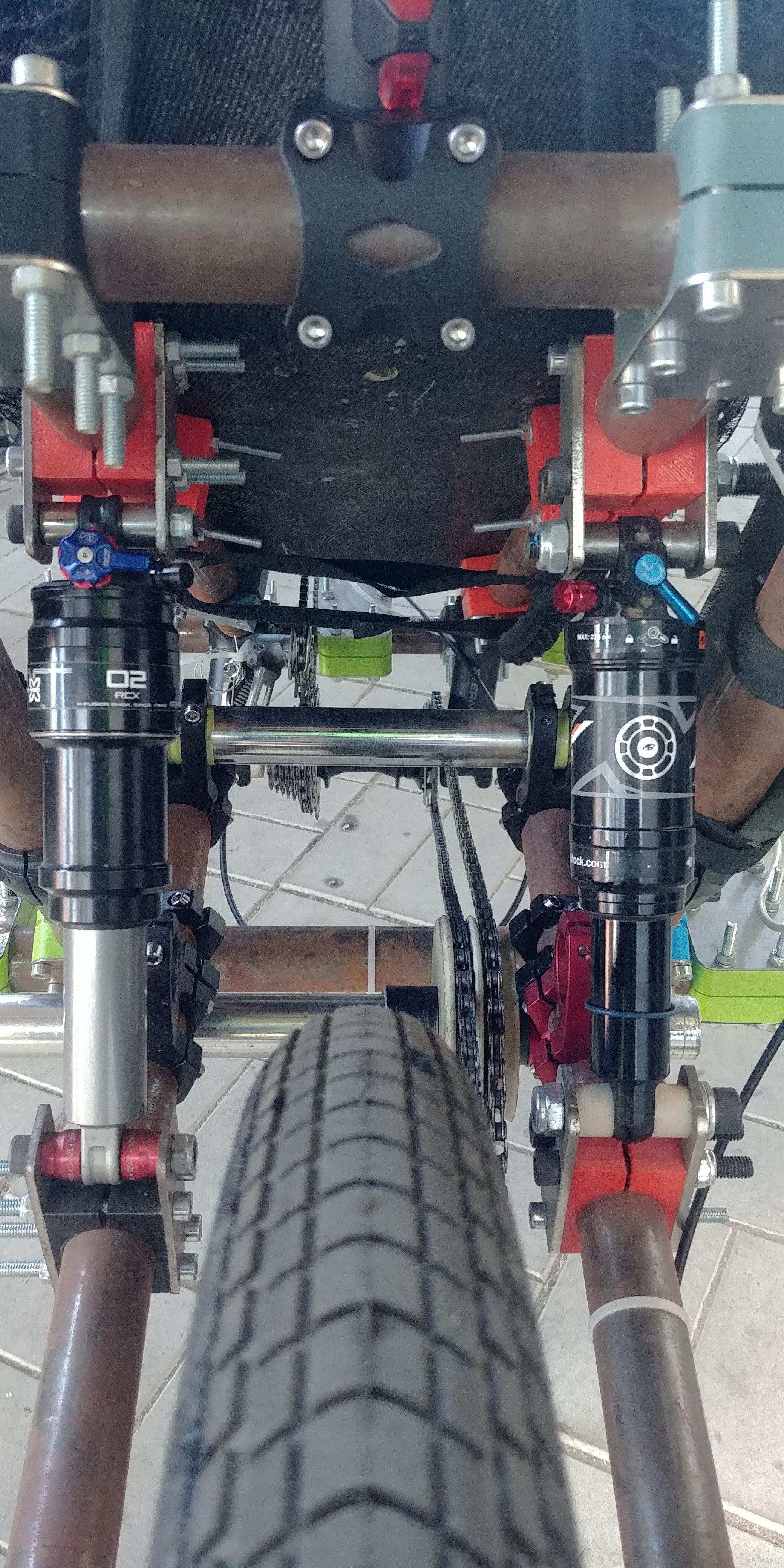
I think it may actually be possible to use such a system as ‘electromechanical’ suspension. Using it as an extra means of electric regenerative damping when paired with cheap shock seems easy, you just need a ball screw to minimise friction (you certainly DO want this system to be backdriveable).
If I and my monster of a bike were lighter, I think it might actually be possible to emulate something like Bose suspension using, say, 1/5 RC car motors that are high speed and capable of swallowing huge currents:

Maybe I should try that sometime, should be a fun project.

Not really. The power requirements are immense for active suspension. Use a semi-active damper like an MR damper, you get 70% of the performance for 10% of the cost. Besides that, fix the bike geometry. Looks like you’re sending all of that wheel load directly into your back.

Also, if you decide to try it, get a motor with higher pole count preferably outrunners with a separate encoder. I have some inrunners, might even be the same ones you linked, and the cogging torque is very high. It makes control between pole-positions unstable.

I guess that depends on what you want to achieve. After all, this is not a car that weight as a ton… It is quite likely that on a really bad road it will drain a lot of power, but than I have a 2kwh battery and I’m not particularly averse of using electric power provided I do actual pedalling.

I really don’t think that active damper is going to fix things that are related to suspension not reacting to small, high frequency bumps - it’s sticktion and suspended/unsuspended mass problem as much as I understand… though it may be that electromechanical system will not really be up to the task either, even if it seems reasonable to me.
I wonder if there are precedents of designing something like this (I know about Bose suspension, but that’s a bit out of my league).

Yea, that’s the whole problem with recumbents. But current position is a compromise of a multiple design constrains… how do you suppose to fix it? Increase WB further? Lower CG further? Not exactly an option in my case.

I would start with a rear trailing arm geometry like https://www.hpvelotechnik.com/en/recumbent-trikes-bikes/recumbent-tech-talk/tech-talk-your-recumbent-with-suspension-offers-comfort-and-safety/

My thought is the best way to use Odrive for something would be see if you can replace the chain with a hybrid-electric drive system where the pedals turn a generator and use a hub motor on the rear, and you eliminate all the complexity involved in trying to get power to the rear wheel in a way the pedal feel does not react to the suspension travel.

1 Like

Well, I already did just that :slight_smile:

Just not odrive but Vesc, odrive is an overkill for that actually. Got 85% efficiency out of the system, too!
I’m pretty proud of it, especially after reading how some companies failed to create a decently effective and pleasant to pedal generator after working on this for years, ehehe.
Maybe they minded the system ‘freewheeling’ too much, IDK. (don’t mind the backwards pedalling - I just happen to like it :))
It works on principles of using duty cycle control mode - as you overrun the motor in power stroke, it resists, but stops resisting on ‘dead spots’. The system is very pleasant to pedal and amounts to 100% automatic transmission, no need to change gears or set load at all, just push harder and the motor will resist harder.

Anyway, I agree that ‘fully active’ suspension that rely on electric motors only is likely a dumb idea - given that Bose’s attempt that that flopped. It boggles the minds the forces and speeds (hence - raw power!) involved in trying to deal with large hits at 100+ kmh on a vehicle weigting a couple of tons!

But when it comes to bicycle speeds and masses (even electric assisted bicycles), it gets a couple of orders of magnitude more manageable, but still I think you got a point - relying mostly on conventional suspension while ‘helping it along’ with electric power (like intelligent damping - I think using a ball screw actuated ‘regen damping’ might be a good idea) seems the best way now I think about it.
I need to give it some more thought.

1 Like

What tmagik said - fix your geometry. At the very least you should probably have a pull-rod system here instead of a push rod, so the spring/damper is joined to bottom frame rail instead of … completely non-triangulated.


This is how the system looks currently.

Here is an other photo:

Yea, the shocks are different but I’ll fix that a bit later. No weld construction is unfortunate compromise due to lack of welding facilities, but it works.
I’m not sure what you mean by ‘pull rod system’ and lack of triangulation - it is triangulated.

What can be upgraded is, perhaps, replacing nylon bushings in suspension with bearings for the system to better react to larger hits, but it does not seem to produce that much sticktion - having plain bearings in suspension is pretty common.

What is the wall thickness on that pipe, you might be within the range of reasonable currents for welding with an ODrive with some inductors on the output…

As for geometry, could you do something like this google draw sketch

Or at least a linear motor damper like the iron-less linear motor at https://www.kollmorgen.com/en-us/products/motors/direct-drive/direct-drive-linear

Interesting suggestion! It should make things simpler indeed.
As for welding with a controller - lol, now that is out of the box thinking! I think it should work indeed - it is just 1.2mm.
However, getting a welding apparatus is not that hard… but don’t skils either and I have cromoly that require gas shielding and my no-weld construction is also ‘self-jigging’ - making a jig for welding from plastic is not exactly a smart idea, it will at the very least melt, or catch fire!
I’m making composite lugs vacuum molded over 3d printed madrels, preliminiarly tests are very encouranging. Plus, I can do that in my living room. Welding in my living room goes one step beyond what even I consider crazy :slight_smile: Maybe eventually I’ll get myself a proper shop, but not now.

No it’s not. You have your shocks mounted to the center of the other tubes creating massive bending moments. To put it simply: