As a quick check of the encoder - run odrv0.<axisX>.encoder.shadow_count, spin the motor 1 full turn by hand, and then check shadow_count again. It should change by cpr +/- a few counts. Did you connect the hall sensor power wires? It’s likely that the hall effect sensors and the incremental encoder are both powered by the hall sensor power. I don’t know the pinout of your motor, but they are probably red and black for power and ground.
For your questions: 1. What is your application for these motors? 2. ODrive does not currently support using both hall-effect and incremental encoders at the same time.
Thank you for your response. I turned the wheel by a complete cycle and i got 173 which us far from 4096. The doc says its the cpr, while it also said its ppr * 4.
My hall sensor wires are:
+5v red
GND black
A(uu) green
B(Vv) blue
C(Ww) yellow
For the 4096cpr incremental encoder, connect the hall effect power +5V and GND wires to J4, connect the A and B encoder wires to J4, and leave the hall effect U,V,W wires disconnected.
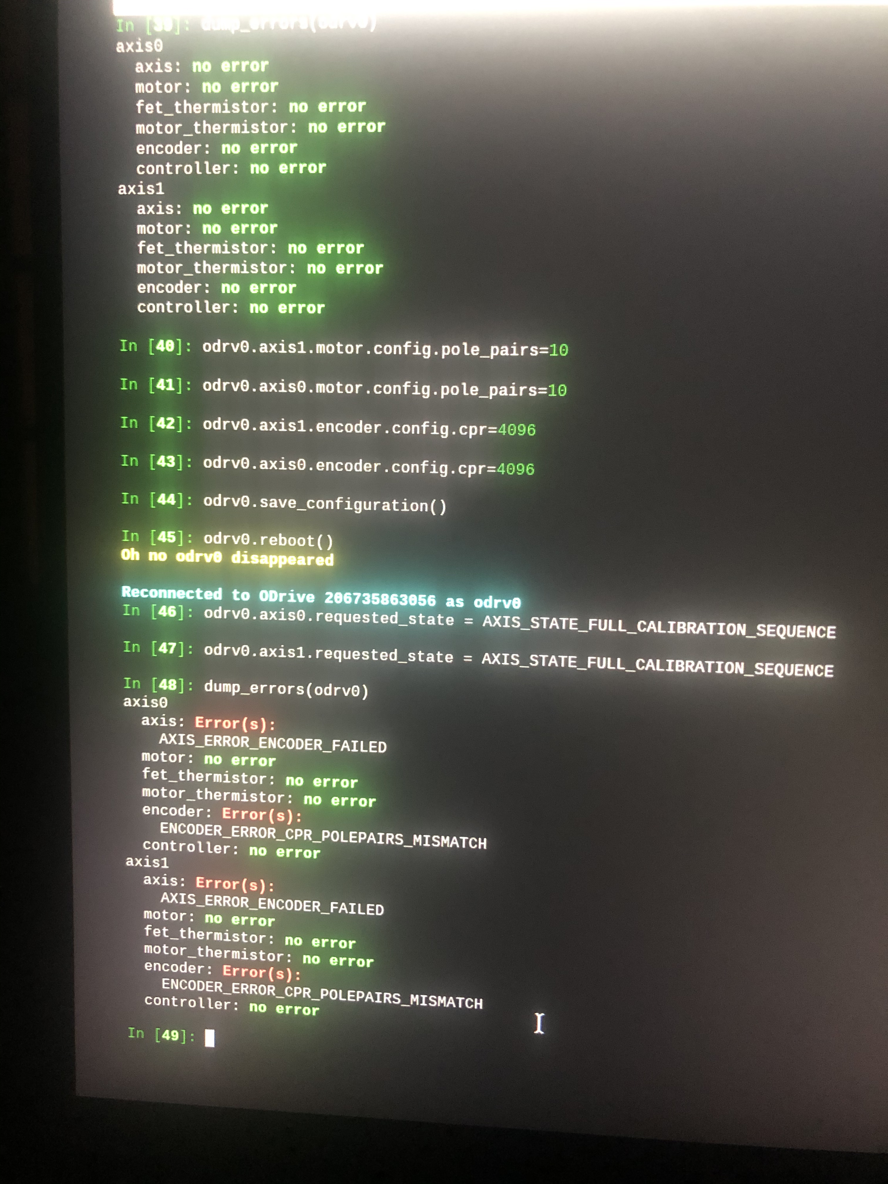
Thank you. I did according to your instruction and i got the same ENCODER_ERROR_CPR_POLEPAIRS_MISMATCH and ERROR_PHASE_RESISTANCE_OUT_OF_RANGE. My motor is 350W.
I disconnected the hall sensor wires (A, B, C) and then connected incremental encoder A and B wire