I’m trying to figure out how to wire the circuits of my rover w/o causing a ground loop.
My circuit has two odrives, an AGX computer connected to both odrives, and three different power supplies for each device. I’ve been researching online for ways to prevent a ground loop and found two different options.
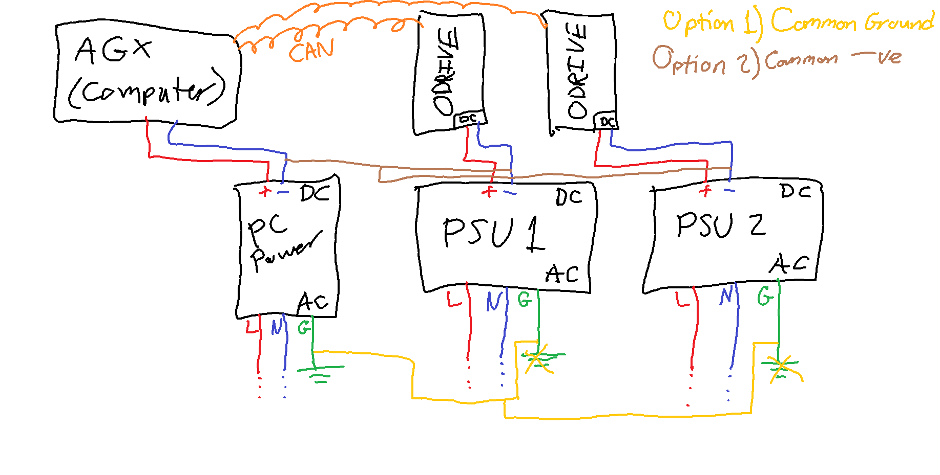
One option is to connect the AC grounds of the power supplies to one common ground. Another option is to connect the DC negatives together.
Which option would help prevent a ground loop in my setup? Is there a better way I could prevent it?
I’m fairly new to this, so I might be confusing some things. I just don’t want to risk frying an odrive or two.
Here’s a simplified diagram of the circuit, with both options drawn out and labeled:
This is pretty dangerous (for the ODrives) because the CAN becomes the common ground.
Imagine the situation where one ODrive loses the negative connection to its PSU (or, because of parasitic inductance in the wiring, the voltage drop across the negative wire is momentarily high) we start to get high currents flowing in the CAN (or USB or UART) connection which is bad news.
What is your application? Is there a good reason to have two PSUs?
(note that the current drawn from the supply is less than the current in the motor. If the motor is turning slowly compared to its max speed, then you will draw very little from the supply, even for high motor currents)
The negative sides should be connected together as close as possible to the ODrive, and you can use an isolated CAN transciever on the AGX.
& don’t forget to use some ferrites on the motor outputs to help with EM noise, which otherwise could interfere with your encoders etc.
We’re currently using PSUs for testing our current design for a rover. Each odrive has 2 motors each rated 24V 5A at max speed, or 240W total. The PSUs supply about 240W of power each, so our test design requires one PSU for each odrive. Our final design would instead use an array of batteries on 6 drives.
What would that look like? Is it just shortening the negative wires or where they’re connected together?
The current path needs to use thick and balanced wire thickness and length, and ferrites so that bulk of the current flows through the correct loop; and these need to be closed loops; This applies to both power and signal channels.
Then, a second, shared ground, arranged in a star-like fashion – coming out of all of the devices, with a somewhat thin wire (relatively higher resistance) meeting in a single point only. This second ground star connection is to balance potentials only and ensure that the device grounds do not go too far off. The resistance of this second wire might be 10-1000x more than the ‘current’ path. Since we only need to balance the base potential and no current, a single wire is enough.
–
unless your power supply specifically tells you not to do that, connecting the source-side ground potential (G) to either +ve or -ve (not both obviously) should be fine. I’d connect them to -ve to make debugging easier; however, I have seen some hi-fi audio amplifiers doing the +ve version.
Hi there. I’m working with @UltraArceus3 on this and we’re having a really hard time finding isolated CAN transceivers. We looked for any premade boards, or chips we could make a PCB with, and they’re practically non-existent. The best we could find was a pi-hat that we’re going to try use it standalone
I know a little bit about electronics, but everything @grey said sort of flew over my head. Can anyone recommend any resources to understand how a ground loop works and how to prevent it? Preferably from a theoretical standpoint w/ equations. To me it sort of seems like magic that current just starts flowing through other wires where they weren’t meant to.
I am working on 3 field rovers and this community scared me about ground loops.
Thank you community.
I use an optoisolator between my PC (Jetson Nano) and Odrive. Since it’s a rover I use DC battery packages and monitor the battery voltage. Was using Dewalt 20v but now am working with 36v
hoverboard battery packages. I consider it part of the design process since I’ll be using batteries in the field.
Was considering 48v LiFePO4 but found out that at full charge the voltage can be over 56v which may damage Odrive . Part of my design decision is to keep battery power between 20 and 36 volts.
So far I have had success with USB optoisolator between PC (Jetson Nano) and Odrive. Also using batteries (20-36v). I have buck converter that changes battery to 5v for power to Jetson Nano.
Not here to change your mind just saying what worked for me!
You can try these: https://www.inno-maker.com/product/usb-can/
I have no idea where they get their parts from, but they have isolated USB-CAN adapters which work out of the box on Linux for not much money.
They don’t work quite so well on Windows actually, but they work fine on Linux.
Right, so the first equation that you need to understand is: V = L * dI/dt
That is: For an inductor (and every piece of wire is an inductor, just as much as it is a resistor) there is a voltage drop across the wire which is proportional to the rate of change of current. (this is in addition to the usual resistive voltage drop V = I*R)
Therefore if you have an extremely fast switch, which tries to turn on-and-off a current source in your circuit in almost zero time, then you will start to see various ‘ripple voltages’ at different points in the circuit, where parasitic inductances (that is, the inductances of ordinary pieces of wire which are not meant to act as inductors) are causing a voltage drop, due to the sudden change in current. These ripple voltages grow proportionally to the rate of change of current in the switch, and for a high-efficiency MOSFET switching at 40kHz as ODrive does, this can be in the range of “GigaAmps per second”, so even a tiny inductance of 1nH could have a ripple voltage of 1V.
If these ripple voltages are severe enough, then there can be a significant AC component of voltage difference between the ground planes two boards, even if they are physically connected by a wire, because that wire has a non-zero inductance.
You can minimise the inductance of a wire by making it straight and short, or by closely coupling it with another wire which always has an opposite current, so that the net current cancels out.
If you have a very short, heavy piece of wire between two boards, then you can be sure that there will never be any significant voltage difference between them. But if the wiring is long, then it can create its own magnetic field, and this leads to inductance, which can lead to a voltage difference at high frequencies.
Scary are only the things that you do not understand. If you are scared, it’s a good hint that it’s time to learn.
You cannot create or destroy a charge.
Charge is a fundamental axiom. Current is the charge moving around
If the current encounters an obstacle, a voltage appears
As long as you allow the current to flow in a single, closed loop, it will be happy, and it will not affect things outside of the loop much. As long as the “upstream” and “downstream” paths of the loop are symmetric, it’s no problem.
If there is more than one possible path for the current to flow, the charge will split according to the impedances along each path. Lower (relative)impedance → bigger chunk of the current will take that path. Conversely, the higher(relative)impedance → smaller chunk of the current will go there. Hence: if you have two paths and don’t want the current to take one of them, simply increase the impedance along that path!
It’s often not all that easy to keep the “upstream” and “downstream” paths perfectly symmetric and balanced. It’s not impossible, but in practical systems there will be some residual, uncorrectable imbalance. It’s also often impractical to eliminate all but one path for the current to take. However, what we can do is control the relative impedances of these paths.
Hence, we need to take care to engineer our systems so that the current flows where it should, and not anywhere else!
Basic, easy-to-follow rules are:
Keep high-current paths short and the wires thick and as physically close as possible to each other; ideally twisted if possible. Concentric cable is even better but relatively expensive. The up and down stream thickness needs to be the same. How thick? use a “wire gauge chart” for reference, e.g. A Guide to Wire Gauge Sizes - Precision Manufacturing Company Inc.
Keep a single point for ground reference. in the entire system. Have all “local grounds” refer to this “global ground” by a dedicated path. This is the “star topology” with one central point and streaks coming out of it. Ideally there should be at most a minimal current flowing in or out the star point;
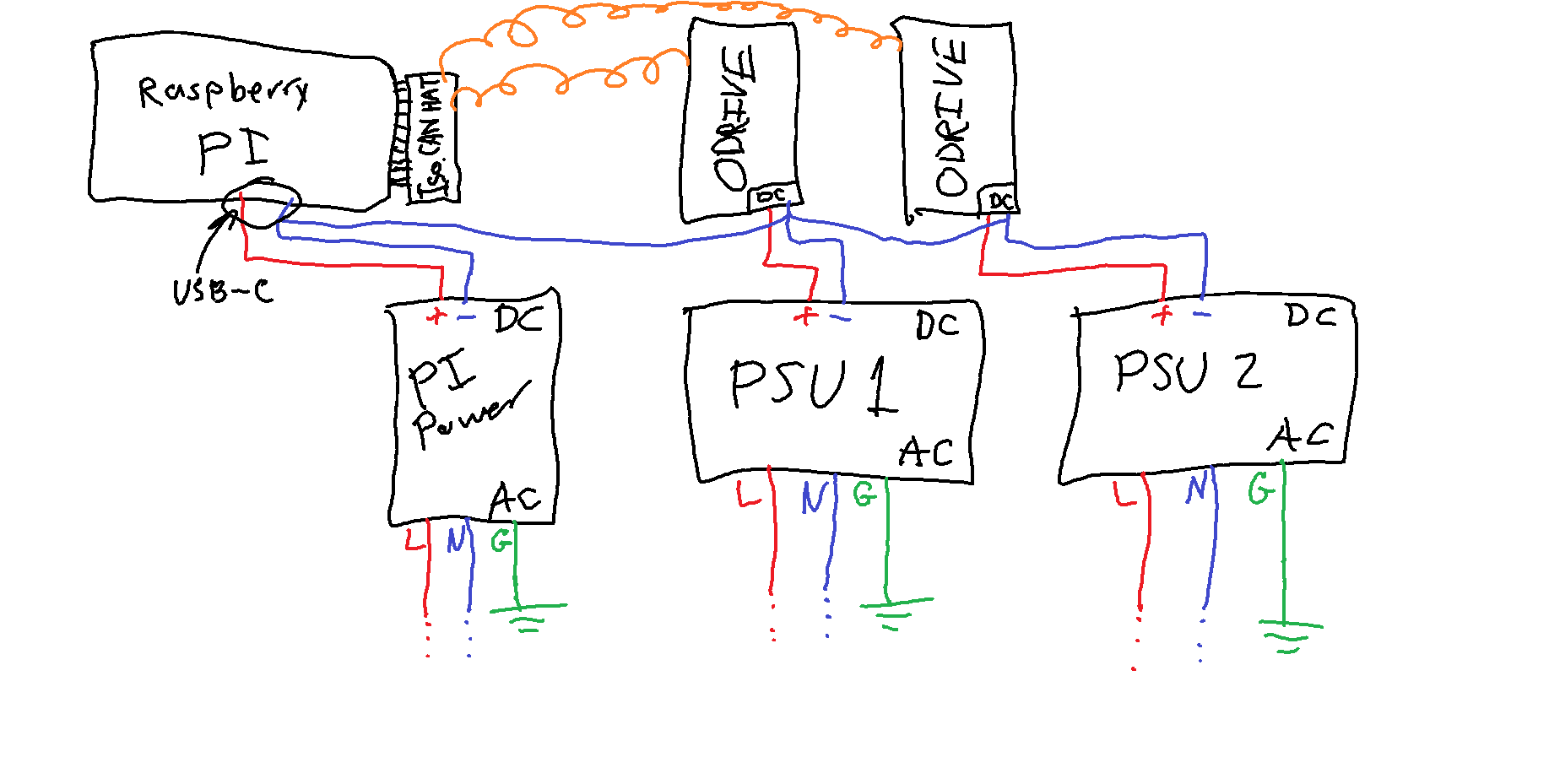
We decided on switching to a Raspberry Pi w/ an isolated CAN HAT.
The connections between the odrive and the hat are three wires: CANL, CANH, and GND.
The updated setup is shown below. Would this prevent a ground loop?
I stumbled across this post from a few years ago again. After a bit more training in electronics I can now appreciate the goldmine of knowledge you guys left here. You all made a made a small, but extremely appreciated, difference in my education!