CNC - Milling - Request for Advice

Hi,

I’ve been researching milling, cnc, and machining for the past couple years. I now work in manufacturing and use a cnc router everyday. I’ve been thinking, planning, and saving for a while and am currently designing my first machine.

First caveat! I don’t have an engineering background. I’ve learned a lot in the last few years but have to admit that when it comes to applied physics and more technical mechanical calculation I’m not confident in my understanding.

I’d like to use Odrive for my X, Y, Z and spindle drivers. I’m planning on using them in step/dir mode to allow me to essentiallly drop them into a standard cnc setup. Mach4 -> Smootherstepper board -> Breakout -> ODrives.

My first question is, “does that make sense?” Am I getting the most out of the ODrive by dropping it into a stepper setup? Is there a better way?

Second caveat! You may have guessed but when it comes to motors there is something that just hasn’t clicked yet. There are a lot of interlocking parameters, different standards, physics stuffs, and such that I just don’t have an intuitive grasp of yet.

If I’m calculating needing a top end HP output of <2hp at the spindle and if I’m using the smaller of the two ODrive motors to drive a spindle like this one am I on the right track?

I’m still in the design and sourcing/pricing phase so I would like to understand a little more clearly what I should be looking for in motor components. I’m drawn to ODrive by the closed loop nature, community and what seems like an auspicious platform to start building manufacturing tools around (I have plans for a 3d printer after the mill).

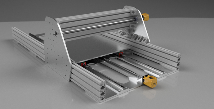
Thanks to anyone willing to advise or point me in the right direction for info. I’ll include a rendering of my current design. Still just a draft to work out size and component requirements, but feel free to criticize it! Please do, in fact.

Drew
This sounds like a very cool project, excited to see how it goes.

For now the best way to do something like a CNC machine is indeed to use the step/dir input.

As for the spindle, it depends on what voltage you plan to run on on, and if torque or speed is more important for your router’s workload. Here’s the decision tree I’d recommend:

  • 48V - use D6374 motor (you will get both torque and speed)
  • 24V:
    • High torque is more important: pick D6374 motor
    • High speed is more important: pick D5065 motor

Happy to answer any more questions. Very excited to follow this build!

Amazing!

Thank you so much!

I am wondering about the base speed of the D6374. I’m guessing base speed just means it’s rated speed and that the rpms listed are that base speed? Can they be pushed above that? Bad idea? I’m really only thinking about the spindle. I’d like to cut mostly aluminum and ~7000rpms is generally about where my feeds and speeds put me.

I will surely be keeping this thread updated with my progress!

Thanks again, I truly appreciate the timely response and interest in my project.

*edit: so I guess I should mention that my plan was to and still is grab two 48v oDrives for driving my axes and spindle.

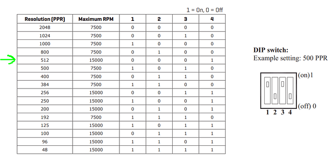
If you use the D5065 motor on 48V, you should be able to get to almost 10,000 RPM. If you plan to use the CUI AMT102 encoder, you need to set it to 2048 CPR (512 PPR), then it will have a max speed of 15000 RPM.

Sorry I missed your reply!

Thank you so much for the info.

Studying the motor spreadsheet a bit more I’m seeing that if I want to get about 1.5 KW out of the D6374 I need to feed it a little more than 45A. Which means a pretty beefy 48v 50A switching PSU for just the spindle. Am I understanding that correctly?

I want to make the right decision in powering my spindle. If I need multiple high current power supplies to run these motors at the torque I need that is adding a lot to the cost of my machine vs. a more traditional AC Motor with VFD setup, and stepper drivers.

Can the oDrive even survive a 50amp current? I’m not seeing any rating in the documentation. Maybe I’m confused?

Again sorry if these are dumb questions.

I’m really wanting to narrow down my hardware and get a BOM together for the final design. Thinking Odrives will be useful at the very least on my X+Y axes and hoping a second one will work out for my spindle/Z axes control.

I’d like the ability to add an ATC eventually and being able to precisely (more or less) position the tool holder in the spindle with the Odrive is a really attractive idea.

Just need to make sure I understand the power requirements.

Thanks in advance!

Hope to update with more pics and info soon!

After looking around a bit more I think I’ve answered all my own questions!

Server PSU’s were mentioned in a previous response to a thread and I also saw that the ODrive is capable of 100A/motor.

That right?

Looked into server psu’s and that seems like a sensible solution. I need to look a little further to figure out what kind of outputs they have and what the limitations they have.

Do people buy these and rework them, or are there models that work sufficiently as is?

I ask because high watt PC psu’s occurred to me as an option but dealing with connectors, and limited options for voltage output made me rethink it.

A bench switching supply with the current requirements look to be around 300+ each, so the server PSU’s seem like a great option if they’re actually capable of 1.5-2kw at 48v through a single output. I feel like they probably aren’t made for that kind of current. Of course, I have no idea.

Anybody have thoughts on PSU’s or links to other discussions here that might be helpful to me?

Appreciate any guidance anyone has to offer!

More snooping and I may have found a viable option.

Anybody have any experience or thoughts on wiring four 12v 1300w (100a) supplies in series to achieve the 48v 100amp ( shouldn’t need more than 50 per motor).

looking atthis in particular.

If I bought 8 of them it’d still be cheaper than a decent setup with stepper drivers and a good spindle, ac motor and vfd setup.

Reading about the amount of power you’re aiming for and looking at the screenshot of your CAD-model I have some serious concerns. I don’t have any dimensions of your machine but with that much power and a frame design like this you’ll run into some major structural problems.
What I’m trying to say is that the frame, the main plate, the machining table, the profiles of the beam and the connecting wings are way too flimsy.
You’ll need a design that is a lot stiffer, that wont flex as much or otherwise you’ll have major issues with vibrations and chatter and dimensional accuracy…

Thanks for the feedback!

It’s definitely an in progress design. At the moment I’m mostly sourcing material and figuring out what kind of working area I’ll have given a the material and components I’m looking/can afford to use.

The gantry will definitely need to be reworked a bit and I’ve decided to just weld up my own steel or aluminum gussets instead of using the prefab ones. Figure it will be stronger and cheaper. That 80x160 extrusion should be solid as a rock, though. And I’ll for sure be mounting the whole thing to a heavy and solid base.

At the end of the day I’m not really looking for that much power. Not going to be cutting much steel. Aluminum, plastic and hardwood are all I am after with this machine. I’m mainly concerned with getting enough power to the spindle motor if I’m going to use an Odrive for that. Figure 2.4kw @ 48v is more than enough to give me ~2hp on the spindle and then have some left over for the a axes.

I haven’t done the math on what kind of power I’ll need to drive the axes yet, but 2.4kw may might end up being enough for all 4 motors. Kinda doubt it but I also have no idea! They’re not designed fully yet so it’s hard to say how much load will be on them.

If you have specific suggestions on design I’d love to hear them. I work with cnc machines in manufacturing but this is the first one I’m designing and making myself. I you have experience with DIY machining I’d be interested in your thoughts!

Thanks again for the feedback!

No that’s not correct in general. The important distinction is that the motor current is not the same as the power supply current. You should dimension your power supply by considering your required voltage and power draw requirement: do not equate the motor current to power supply current.

Please see this thread for details on the current handling capability as a function of cooling: Odrive MOSFET temperature rise measurements using the onboard thermistor.

Did you get anywhere with this? I am in the process of modifying a Denford Starmill to run the X and Y on ODrive. The Z as it stands will be running a stepper and the spindle will be a 1.4kW 180VDC motor. I run a similar machine at work and have a spindle power output read-out i find that the spindle rarely climbs above using 500W. I plan in the future to upgrade the Z axis to odrive and either add a 4th axis or run the spindle off the same drive.

For a completely unrelated project, I took eleven, 12V 30A rated power supplies and wired them in series to supply a 130V DC bus. Strictly speaking, that’s more wattage than can be drawn from a standard wall outlet (15A @ 120Vac= 1800 W) But it worked for my purposes.

Hi!

Thanks for your interest.

I am making progress. Currently I am working on the spindle deign and trying to get that finalized. Planning on shrinking the whole thing a bit and making it more of a learning platform.

I have nailed down most of the electronics, and figured out the power supply.

I’ll be stringing a set of server psu’s in series to get the 48v ~70a from a 120V wall outlet. If i can figure out a 220v hook up in my work space I can get 100a from the same setup.

Depending on how things look from there I may add another psu stack.

For your spindle it sounds like maybe you’ll want to find a VFD to match? I’m planning on driving my spindle with a bldc motor, so 48v is easy (cheap) to get with a few 12v switching supplies wired series.

I keep meaning to post some update pictures of my spindle design, but I’ll get around to it eventually.

The motor is dc so a VFD wouldnt work. They run off a thermistor drive dc controller. I have everything set up and almost ready to go. Would be very interested to see your build.

Ah, nice. I’m not familiar with those. I’ll have to look into it.

I’m working my way back out from the spindle. I’ll update with more current designs as I get them together.

The actual build will probably be a long term project, but I’m hoping to get some of the electronics and motors together soon to start testing things out.

I’m in the process of designing A CNC bridge mill myself and just wanted to give you some inspiration.
for the power supply im using HP 253232-001 226519-001 ESP120 2950W Proliant Power Supply 200-240V
real easy to interface to and cheap.
here is a link to some recources, https://www.rcgroups.com/forums/showpost.php?p=23062346&postcount=643