today I carefully studied the PWM time sequence and digged little deep about the the function
“ControlLoop_IRQHandler”. I mad a diagram about the interrupt sequence for better understanding and communication. A few information maybe wrong in this diagram, I would improve it after disscusion.
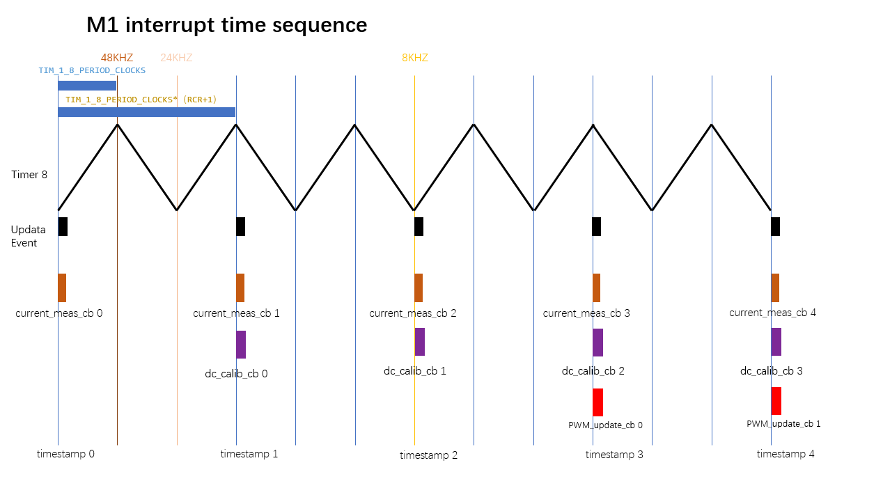
I just put motor M1 here for better presentation, and here is my understanding. point it if I am wrong :
tim 1_8 frequency is 168Mhz, according the timer set up: Prescale=0; Periode =TIM_1_8_PERIOD ( 3500), we can get the frequecy count up/down to 3500 = 168Mhz/3500 = 48Khz. That also how the black triangle wave been drawn in the diagram.
The " RepitionCounter = TIM_1_8_RCR (2) ", which means the interrupts happens 16Khz (the black square in the diagram) .
the callback functions ( current_meas_cb(); dc_calib_cb(); PWM_update_cb(); ) all updated in every timer interrupt (after timestamp3) ?
For update 0, if "current_meas_cb() " happened in timestamp 0, then the corresponding "dc_calib_cb() " happened 1 timestamp later, then “PWM_update_cb()” 3 timestamp later?
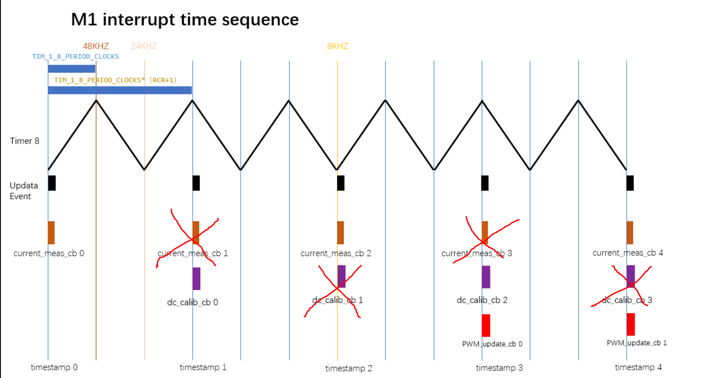
The mistake I made is: I didn’t notice the following code is only called when counting down:
if (!counting_down) {
    TaskTimer::enabled = odrv.task_timers_armed_;

    // Run sampling handlers and kick off control tasks when TIM8 is

    // counting up.

    odrv.sampling_cb();

    NVIC->STIR = ControlLoop_IRQn;

}
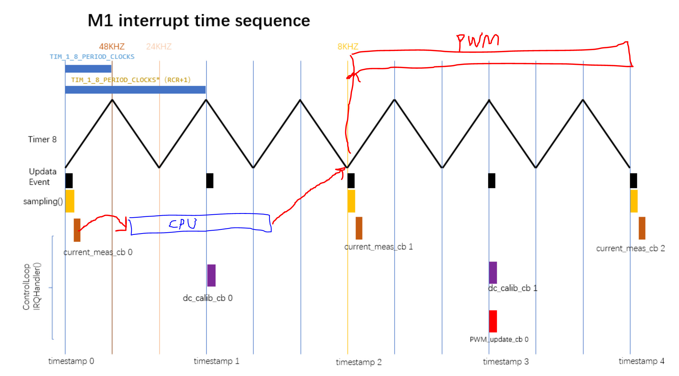
The current is sampled, then the CPU uses the data to compute the control loops etc, then the resulting PWM timings are loaded into the shadow registers and go live on the “current sampling” corner shown.