So a few people have asked me about the motor timing diagram, and what exactly is going on. I kind of just stuck it there for making sure it doesn’t get lost, and I apologise that there is no legend or any other explanation. So here goes.
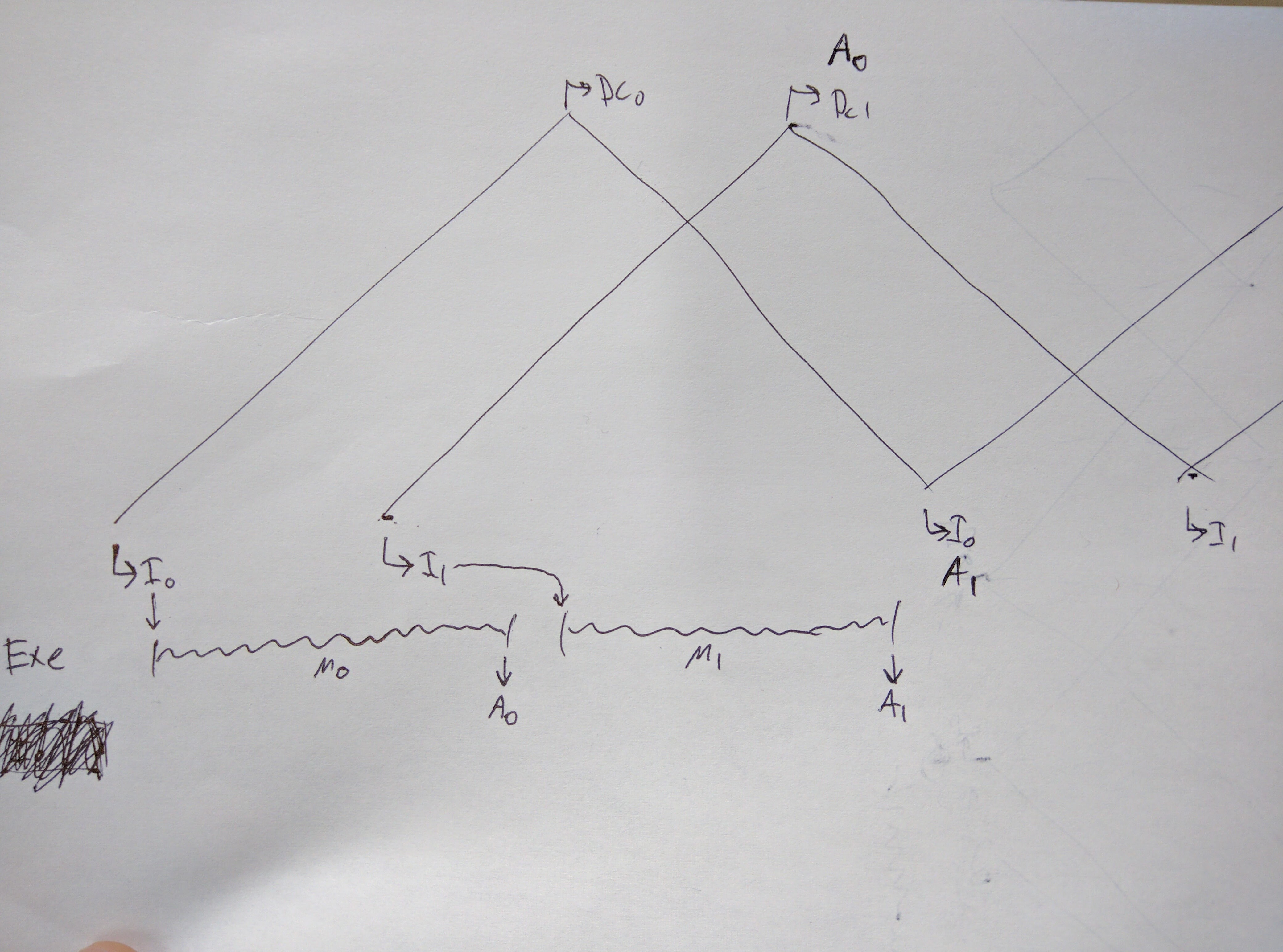
First: the diagram reproduced here for easy viewing:
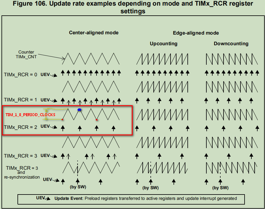
So some background: we are using Center Aligned PWM, which looks something like this:
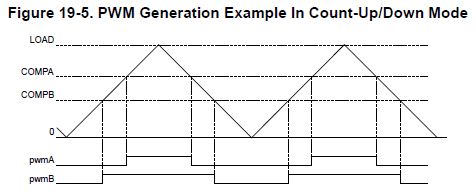
And that triangle wave is the counter value in the PWM module, and is the same triangle wave we have in the first diagram, except that we have two of them, one for each motor. The leftmost one drawn belongs to motor M0, and the other one to M1.
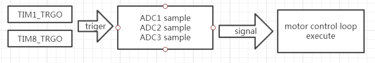
We wish to sample the currents at the time when all PWM signals are low (explained more here), so we set up the ADCs to trigger on the point where the counter reaches 0. This is marked as the I0 and I1 points on the diagram. When the ADCs finish sampling, they fire an interrupt, the pwm_trig_adc_cb. This interrupt then wakes the motor control thread, and we execute the control code: this is the squiggly line, the control code execution.
Actually, we run the ADC and interrupt on the top corners too, labelled DC0 and DC1, but here the ADC’s measure no current, and we use this to calibrate away DC offset. This doesn’t wake the motor control thread, the calibration is done with a filter in the interrupt. Also, we don’t want the motor thread to write to the PWM registers as soon as it has new results, since high priority interrupts can cause a small jitter in the duration of motor thread execution time. So we queue the value and apply it at a known time. Note that the PWM hardware loads new values from the compare register at every corner.
So in more detail, for M0:
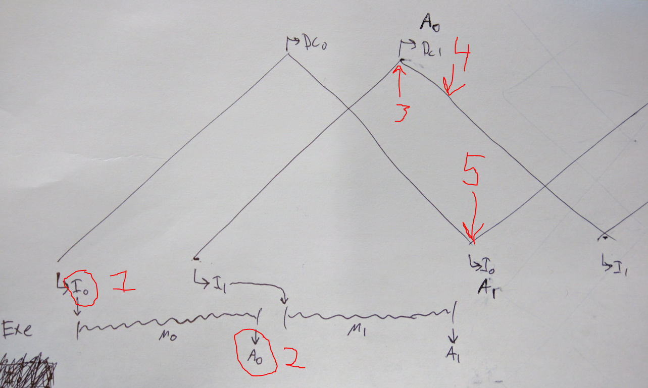
- ADC measures M0 current, control computation starts
- Control computation finishes, we have new result A0 to be put on PWM
- Trigger interrupt that will write to PWM hardware (A0 labeled corner)
- After short interrupt code execution time, we write to registers
- PWM unit reads registers and uses new value
So the control latency (current measurement to PWM goes live) is exactly one current-measurement period.
Let me know if there was anything that was unclear, and I’m happy to expand the explanation.
Also, if someone is interested to transcribe this to a sensible location in the repository for documentation, that would be more than welcome! ;D
Cheers.