Can Odrive work on sinusoidally-wound, and not only trapezoidally-wound, PMSMs? Planning on using these in an upcoming project, and using the ODrive to get better controller performance.
Many people call hobby brushless motors BLDC’s (implying trapezoidal back-emf). However this is usually wrong. Most hobby brushless motors are PMSM’s with sinusuoidal back-emf. Hence ODrive is using Feield Oriented Control, which drives sinusoidal currents, and is optimal for PMSMs. Put another way: Yes ODrive works well on sinusoidally-wound motors, and not-so-well on trapezoidal ones.
I had a look at the specs of the motors you linked, and these kinds of motors should work well with ODrive. One thing to keep in mind is that these motors are wound for higher voltage and lower current than the motors ODrive is designed for. Hence you might not reach a very high top speed.
We can calculate the max speed you can get with ODrive. The current version of ODrive have a max bus voltage of 24V. We can look at their datasheet, and find their Back EMF (Ke), [Vpeak/kRPM]. We assume this is a phase-to-phase quantity, given that is how they specify the resistance and inductance.
We also note that Space Vector Modulation (SVM) has a full-modulation voltage of sqrt(3)/2 or around 87% of the bus voltage, and that current versions of ODrive leave 20% modulation-time for current sensing.
Therefore, we get a max line-line peak voltage of 24V * 87% * 80% = 16.6V. This means that for their fastest motor, you can hit 3600RPM on their fastest motor, and only 450RPM on their slowest.
Future versions of ODrive might allow 48V bus voltage, which will allow double the top speed. Also we might do current sensors on 3 phases (instead of 2 currently), and can therefore not require the 20% modulation time for current sensing, and hence further raising top speed by 25%.
2 Likes
Thank you for your detailed reply, and sorry for not responding earlier.
I did know that the bus voltage for the ODrive is currently 24V and that I’d need more voltage to go full speed (I think these motors are rated to 75V max). One thought was just to use the ODrive as the brains and to use more FETs and a higher voltage bus to drive the motors if more speed was required. This would be a proof of concept, so I’m not overly concerned about cost or how elegant the solution is in the short term.
I didn’t know about the upper voltage limitation using SVM, or the 20% time spent for current sensing. I imagine I’ll be able to read up more on SVM, but could you point me to a resource to learn more about the 20% time spend doing current sensing? Adding another current shunt wouldn’t be cost prohibitive at all in most of my projects, especially if it removes the 20% effective bus voltage decrease, as you’ve suggested. Are there other considerations here to take into account that preclude removing the current sensing time?
You know ODrive is mostly FETs, gate drivers and a microcontroller. Once you have other fets and power routing, then you should probably just go for your own board completely xP. Just wire up the microcontroller in a compatible way. Though if you want to save yourself the trouble, you can wait until ODrive v3.4 comes out, which at this point I think we will do a 48V version.
Still, 48V is not 75V. Though, not something everyone knows: it is actually possible to go faster than base-speed through something called field-weakening. This can be done with a modified control law (basically with firmware). It is less efficient than turning up the bus voltage, but for moderate speeds over base speed, it can be worthwhile the cost-savings in the inverter.
So to your SVM and current sensing question: The modulation limit comes from the size of the circle inscribed in the SVM hexagon is sqrt(3)/2 times as big as the space vectors, as can be seen in the diagram below. I appreciate that this doesn’t explain why it is a hexagon to begin with: please check page 178 of this writeup for some excellent insight.
SVM hexagon with max-modulation circle inscribed.
When it comes to the current sensing and how we have to back away from the modulation limit to do current sensing with only two shunts: Let me first explain how and why we are doing the current sensing.
We are doing “low side current sensing” also known as “inverter leg current sensing”, as is labelled in the following diagram. Putting the current sensing on the phases requires either galvanic isolation, or differential amplifiers with high bandwidth common mode rejection: both of which are expensive. More info on different topologies and strategies can be seen in this application note.
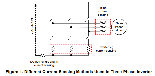
So why sample on only two phases? From Kirchhoff’s Current Law, we have that the phase currents must sum to zero. That is, if we have 1A going into phase A, and 2A going into phase B, there MUST be 3A coming out of phase C. So from this constraint, we only have 2 degrees of freedom, and hence knowing any 2 phase currents is sufficient. This is also why the DRV8301, the chip that ODrive v3 is using, only has two current sense amplifier channels.
However there is one limitation with this specific combination of low-side sensing and only using two channels, which stems from the fact that we must have the lower fets connected in order to see the current, as can be seen in the above diagram. If you are at full modulation, there will be some point in time as the rotor turns where some sense resistor’s fet will get 0% duty cycle, and you can’t measure the current. If we limit the modulation to 80% of full, we guarantee that we will be in state S0 (all lower fets on) at least 10% of the time (the other 10% is in state S7, all upper fets on).
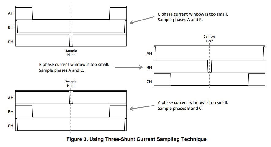
By using 3 shunts instead, we can use the strategy illustrated below to overcome this issue. In a future major revision of the board, where we change from the DRV8301 to a different chip, we may do exactly this.
4 Likes
Hi,
is this information still up to date with the latest versions?
Odrive is still works well on sinusoidally-wound motors, and not-so-well on trapezoidal ones?
1 Like