The wiring is as follows:
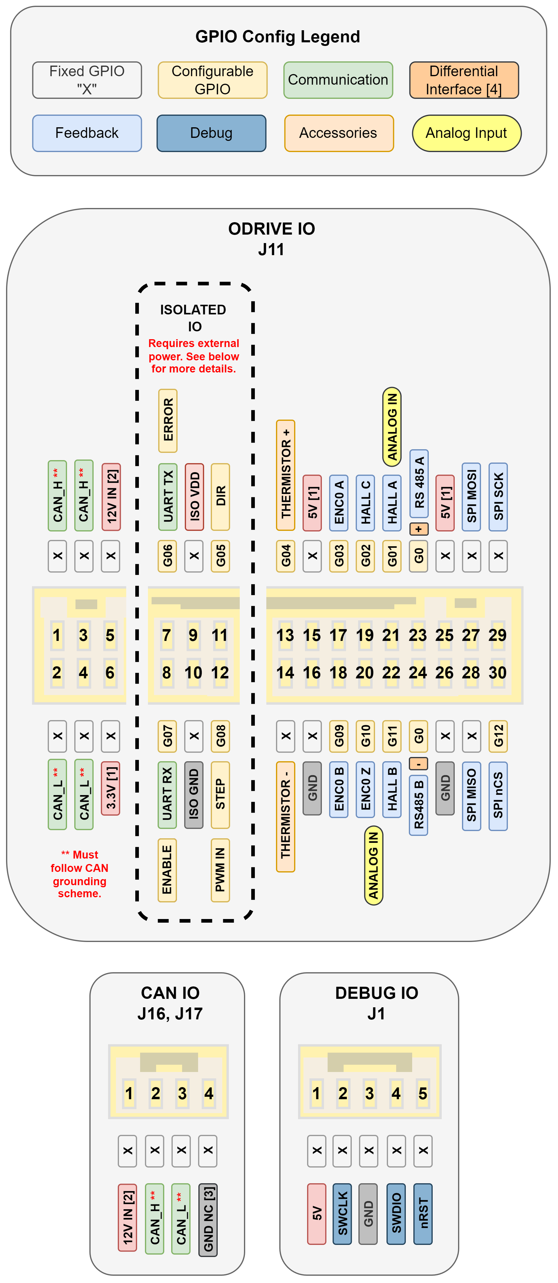
Arduino 5V → ISOLATED IO J12 Pin 1 (ISO VDD)
Arduino GND → ISOLATED IO J12 Pin 2 (ISO GND)
Arduino Pin9 (PWM) → ISOLATED IO J12 Pin 3 (G08)
On the Arduino side I have tried both: ‘analogWrite’ and the Arduino servo example to generate PWM signals for position control. I keep getting this error on the ODrive side:
active_errors: Error(s):
ODriveError.MISSING_INPUT
Hmm, I am not seeing anything immediately wrong with this setup. It may be that the Arduino PWM output does not match what the ODrive is expecting, the Servo - Arduino Reference library handles this nicely so you don’t have to worry about the PWM signal frequency. You mentioned you did try this, could you please share the Arduino code you are using?
In general, for debugging PWM inputs I would suggest leaving the ODrive in IDLE, and plotting odrv0.axis0.controller.input_pos (or whichever endpoint you want to command with PWM) in the GUI while you sweep through the PWM outputs from the Arduino.
Hi,
I’m trying to velocity control with PWM on ODrive S1.
The RC PWM signal is input to G8 according to the wiring diagram. The wiring is the same as Eisa’s one, but the “input_vel” is always “nan”.
Even if the PWM pulse width is changed to 1000 us, 1500 us, or 2000 us, it is always “nan” as well.
How are you sending the PWM signal, from an RC controller or an Arduino? Nan is the expected value if there is no PWM signal (more specifically a signal with a high time between 0.5ms and 2.5ms).
Also make sure there are no other endpoint properties trying to command input_vel (or input_pos/whichever endpoint you want to use) as these will be in conflict with the signal into G08.
Thanks for the reply.
The cause was in the RC controller.
When I released the fail safe in the RC controller, the PWM signal was sent to ODrive and “input_vel” changed as expected.
Result of input_vel :
In [12]: odrv0.axis0.controller.input_vel
Out[12]: 1.5995585918426514
It is very important that the ODrive goes into a safe/idle state if/when the RC receiver looses communication with the remote control, completely disabling the fail safe can be dangerous and should only be used for testing/debugging in a controlled environment.
New user here, trying to use a S1 with PWM input, but also getting input_vel = NaN
I have the PWM controller connected on J11, pin 12 (G08). I confirm the PWM signal is on that pin with an oscilloscope. I tried debugging by reading the GPIO state
This will only return 4, 6, 2048, 2052, corresponding to the 3 hall sensor pins, G01, G02, G11. bit 8 is never set, even though I connected it to 5V. I also tried the same test on for G07. Am I not setting the pin configuration correctly for reading (i.e. does GpioMode.DIGITAL mean input or output?)
G08 and G07 are both in the isolated block of pins, are you supplying ISO_VDD and ISO_GND from the Arduino? Is sounds like the isolated IO are either unpowered or the isolation IC is fried.
GpioMode.DIGITAL can be used for inputs and outputs, both set_gpio(<N>, <mode>) and get_gpio_states() will work with this mode. However, if you have gpio8_mode = GpioMode.DIGITAL with a PWM signal on G08 the reading from get_gpio_states() will be noisy garbage.
Ah, I didn’t connect ISO_VDD or ISO_GND. Thanks for the tip. Now it’s fine, but I connected it to the Odrive’s 5V, which I know will defeat the purpose of isolation, but I don’t see any other PWM pin to use.
GpioMode.DIGITAL can be used for inputs and outputs
OK, I think what you mean is the default state for all pins is input, but set_gpio automatically changes the pin direction to output. Neat.