i used mosfets with higher current rating and therefore was able to use only one instead of two. with proper thermal management (use of heat sinks) these mosfets should be able to handle more current than the original design. once again i havent tested the design thoroughly enough to validate all the edge cases( mosfet gate charge timing etc) and power limits but so far it looks good.
i am actually away from my workshop due to covid19 so couldnt test the boards further.
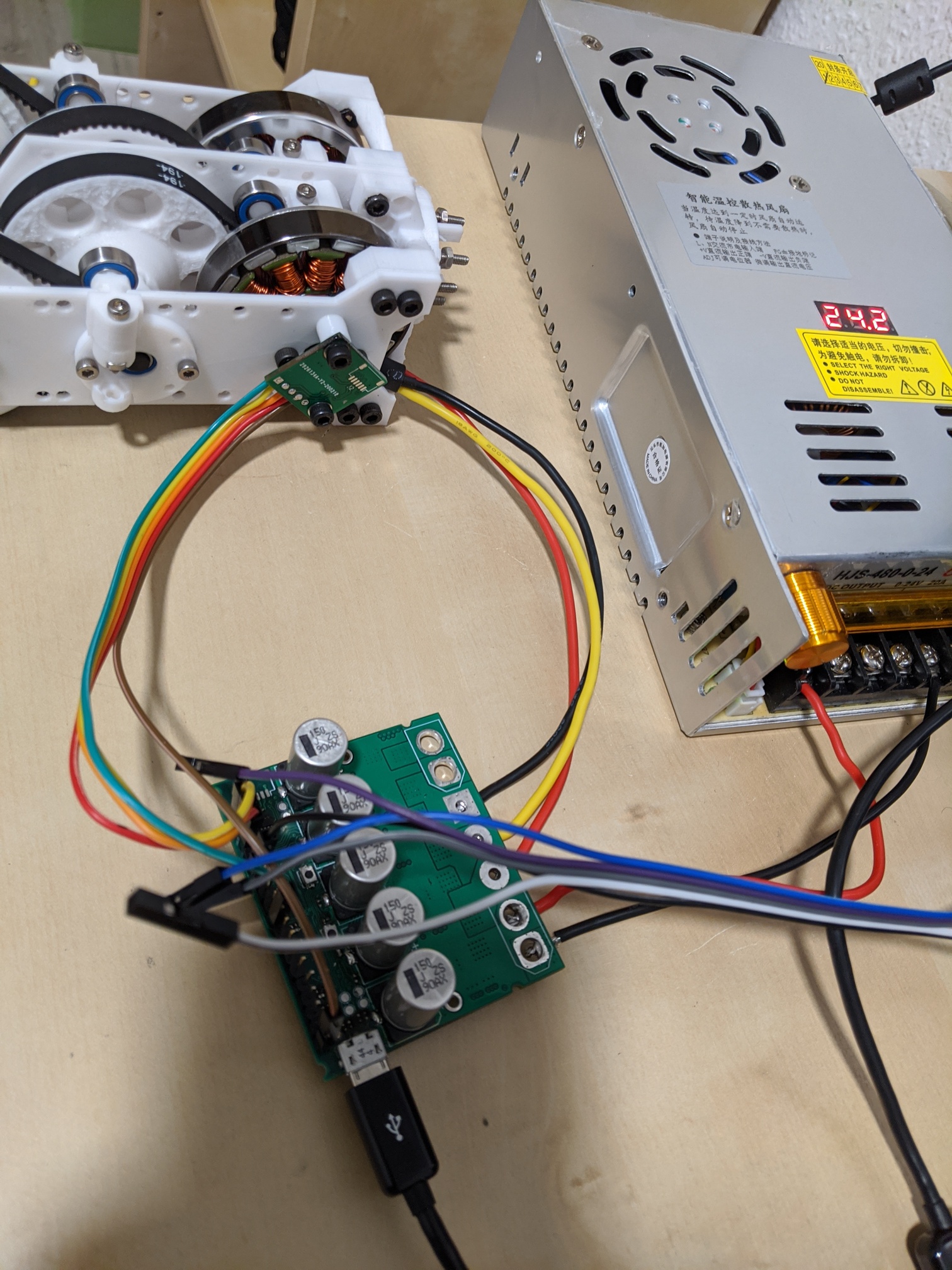
Hi Guys, i was finally able to test the pcb with an encoder. everything including the encoder pcb is functional. i was able to calibrate and move the motor to the desired pos using odrv0.axis0.controller.move_to_pos().
there was one issue where the odrivetool was not able to communicate with the pcb and only when i connect the programmer i was able to communicate. but upon further debugging it turns out if i only connect the GND of the programmer it works. this means there is probably a missing solder connection on the USB connector (as it was very hard to solder by hand) and the programmer was able fix this missing connection between the pcb GND to the GND of the computer. with proper soldering this shouldnt happen.
i ordered parts for only two boards, i think it was roughly 150euro for 2x controller pcbs and 2x encoder pcbs. its not very economical at low volumes. but if you need a smaller pcb or are ordering more than 4-5 controller boards then its better. uploading the mouser ordered cart to the repo for reference.
I’ve read the whole thread, amazing work! I have a small issue that you might know how to resolve.
I have been using a modified one axis ODrive (based on firmware 3.4-24v) with the odrive tool v4.12. The only thing that was modified in the “custom” firmware, was the shunt resistors i replaced with 0.015ohm. Everything worked quite well, until i updated the odrive tool to v5.1. I noticed new attributes and methods. This lead me to update the firmware with the latest version. Once again, i only modified the shunt resistor values to 0.015ohm, and i expected everything to work as before.
Unfortunately, it did not. I tried to run the simple command odrv0.axis0.requested_state = AXIS_STATE_FULL_CALIBRATION_SEQUENCE, but nothing moved.
Do you have any idea about the firmware changes? Is there something in the firmware that requires the second axis? Is there some sort of “ping” the processor expects from the second axis?
Hi
sorry for the late reply. just checking today. havent looked into the firmware so cant say for sure if thats the issue or not. but changing the resistor values definitely changes the voltage drop across it and therefore the current sense readings. if you can change the current limit then maybe a quick test can be setting the max current limit and seeing if it works.
Hi Azmat,
first of all, thanks for your effort and generosity to share your board, something I was looking for as I want to use it in my CNC, so today pulled the trigger and ordered a few, hopefully, they will perform as expected. I found one more similar project. The question though still remains as Zxx-Eric pointed out, did you get clear why the new release is failing? I am new to this community and don’t know yet how the project works, question if they consider custom HW as for example this is done in the Vesc project?
@parasole and @Zxx-Eric
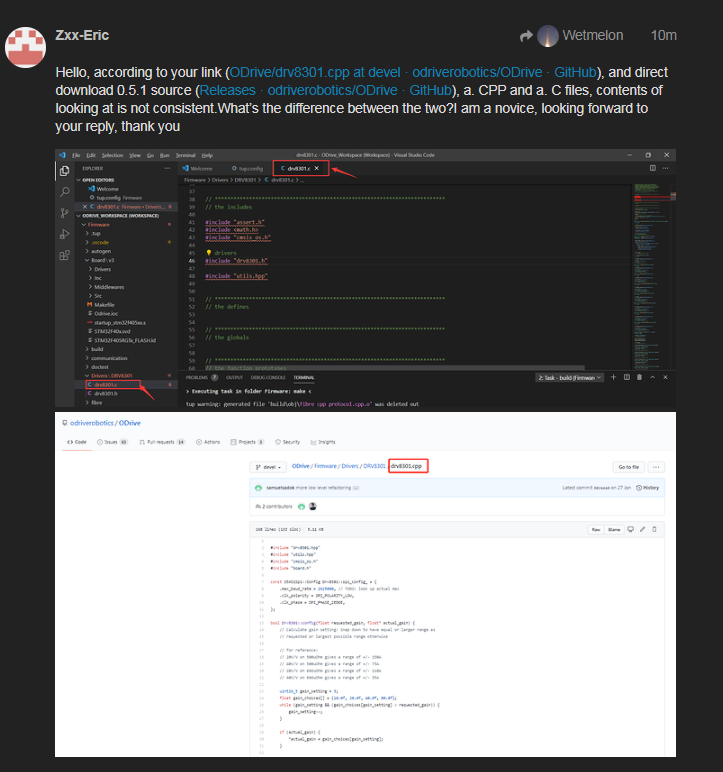
regarding the issue with FW v0.5.1, i found this issue where the new FW waits for both drivers to get online ([SOLVED] New firmware & odrive tool v5.1 for 3.4-24v custom board, one axis) and most probably this is the root cause for the FW not working. the solution seems to be straight forward i.e. commenting out some code. though you will need to compile it.
Thank you for sharing your amazing work. I’m currently working on a single channel BLDC drive of my own and I looked over your design. I have a couple questions:
Why did you use low side current sensing as opposed to phase current sensing? I know the Odrive does this but it seems simpler to me to measure the phase currents. Does it help you catch a shootthrough?
What’s the function of the 2.2 Ohm resistors in series with the mosfet gates? I was under the impression that adding resistance in that path will slow down the switching.
What does the braking circuit control? As in what’s connected to J9?
I didn’t design this single BLDC drive but I think I can reply to some of your questions :
-I think he used a low side current sensing because he took example on Odrive design.
-The 2.2 Ohm resistor in series with the FET Gate is there to limit the current drawn from the gate driver, which can’t supply an infinite current.
-The braking circuit is here in case your driver is powered by a power supply that can’t deal with regenerativ current. During braking (when torque and speed are in opposite directions), if the current can’t flow back to the power supply, the DC Bus voltage will increase a lot and can damage your driver or power supply. So you can plug a braking resistor on J9 and enable the braking function. During braking, it will connect the DC Bus to the braking resistor with a variable PWM to avoid the DC Bus voltage to rise too much.
It posible not used the drv sir?? I want coustem like a vesc 75100 or bigger more. So they not used the drv again. I dont know if i do it must change the frimeware or just build sir. Thank you🙏