Does Odrive have a load observer + feedforward for compensation of changing loads?

Hello!

I was just wondering if the current version of the firmware has any load observer which uses its output as feedforward to compensate for external changing loads or disturbances.

I looked for it in the forum but I didnt find anything, and I think it would be easy to implement, and also, it would not interfere with the current control scheme (i.e., FOC with PI controllers for feedback). It would just be an “add-on” with independent tuning.

Jorge.

Take a look at the RazorsEdge branch - you can enter the load inertia, and it will calculate appropriate feedforward terms.

However, I don’t think it has a load observer as such, i.e. it will not work out the inertia value for you.
Torque units are changing from Amps to Nm though, which helps you if you are trying to make such an observer yourself.
Maybe you could do it in your python code, by measuring the torque for a given acceleration and settng the inertia value like that.

Tom

Hi tom!

I had a look at what you said, but the feedforward you talk about is only for the acceleration command, if im not wrong.

I dont suggest any complicated observer that works as an adaptative controller and calculates inertia and viscous friction in real time. Rather, i suggest a very simple observer which uses the measured speed and quadrature current (i_q) as inputs, and a mechanical model of the system to predict the output speed. Then the difference between measured and calculated speed is passed through a PI controller (independently tuned) whose output is a torque feedforward compensation term, which enhances a lot the capability of the drive to reject external varying disturbances (i.e., improves the sensitivity function)

For this, obviously a first order model of the mechanical system is needed, made of simply a gain and a time constant, which can be easily calculatd by applying a constant i_q current and looking at the transient and steady statevalue of the speed, for example.

I will try to draw and add a diagram to show here what i mean.

Cheers
Jorge.

Hi Jorge,

If you could upload a block diagram that would be great.

If we know the inertia of the system then we should be calculating current feedforward terms in all position or velocity commands. It sounds like your idea is to calculate the feedforward term, measure the response, then adjust the term to account for changes in the plant dynamics over time?

Also, why 1st order? Mechanical systems are typically modeled as a 2nd order as in

\begin{align} \frac{X(s)}{F(s)} = \frac{1}{ms^2 + cs + k} \end{align}

I think 1st order is referring to torque -> speed. The position part is sort of uninteresting in terms of dynamics, since it will always just be the integral of speed.

I think the PI load controller is what we have already in the velocity controller though, we are just missing the mechanical model feed-forward.

Oh right, duh. I even included it in my transfer function that the output is position while we’ve been talking about velocity.

That’s kinda what I was thinking. This is very similar to the velocity filter

Hi guys,

So here I explain a bit more what i meant.

First of all, let’s start with an assumption: the inner current control loop is fast enough that can be neglected by the motor dynamics, in order to simplify the analysis. So lets assume that the equivalent transfer function of the current closed loop and electric model of the motor is a 1.

Then, by applying the motor torque dynamic equation we have that:

Jws = Kt*Iq_ref - B w - T (laplace domain)

Where J is inertia, Kt is motor constant, B is viscous friction, T is external load, w is speed, Iq_ref is quadrature current and s is the laplace operator. The motor model is then a first order system which can be expressed as a gain with a time constant.

Since Kt is a constant, that expression can be written also as: J * w = Kt * Iq_ref - Bw - KtIq_load, where T = Kt * Iq_load. This means that Iq_load is equivalent to the external load, but scaled with the Kt factor. I do this because then you can identify the whole system as a gain and time constant, otherwise you would need to know the Kt factor (which is not always available).

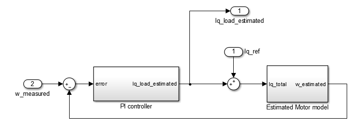
Then, the load observer that I suggest is this one:

So as I said, it simply uses the information of the identified plant to estimate a velocity, which is then compared with the measured velocity, and the error is passed through a PI controller. Its output is the estimated Iq_load, which, when summed to the Iq_ref, is the input to the mechanical model of the motor.

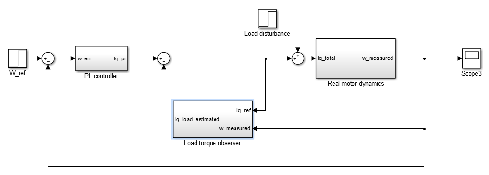
Once we already have the observer, its output (Iq_load_estimated) can be substracted to the calculated Iq current of the speed loop like in the following picture:

As I said in my previous message, to implement this only 2 things are needed:

  • identifying gain and time constant of motor dynamic model
  • tuning the PI controller of the observer

For the identification, it can be done by applying a step in the Iq current and then observing the settling time and gain of the speed. The PI controller of the observer can be set with the same parameters as for the PI of the speed loop, for example.

I have experimentally applied this control structure in another motor drive that I develop and it improves quite a lot the disturbance rejection, which is extremely important in CNC machines.

I hope my explanation helps to understand it! :smiley:
Jorge.

1 Like

I feel like this is very similar to the velocity observer already implemented, except the output of the observer influences the estimated rotor position and velocity instead of directly affecting the torque setpoint Rotor Encoder PLL and Velocity. I’m not sure how the two would interact exactly

Hi wetmelon,

Yes, indeed, the concept is similar but applied to a different variable, in the case of the rotor velociry PLL.

In that case, you make use of the fact that the relationship between speed and position is always the same and exact:

Position = 1/ s* speed

So the only thing to do is to tune the PI controller to filter more or less noise (basically change the bandwidth)

The two observers can perfectly live toguether (if tuned properly obviously) because that is precisely what I am using in my implementation. Two independent observers, one for torque load and another one for speed. And because thats what state observers like Kalman filters do (keeping in mind its differences), which is, estimating all those state variables (currents, speed, position and load torque) by mixing the mathematical models of the motor and the measured values.

Cheers!
Jorge