Driving, decelerating, and generating modes in the GUI

Hello ODrive community,

we have a somewhat unusual rotating system, and I have some more detailed questions about certain aspects of the ODrive Micro to ask later, but let me start with the most basic facts of the problem.

We have a large rotating mass that is externally accelerated from zero, rotates for a while, and then is externally stopped. We intend to add a small motor geared to the mass that would reduce some of the perturbations in the rotation that are introduced by the non-ideal external drive. So with respect to the load, we want to be able to accelerate it and decelerate it by small amounts. AND, since our small motor is battery operated, we would like if possible to recover some of the energy during deceleration, especially the end-of-operation deceleration. There are other considerations, but that’s one half of the nutshell explanation.

The other half is that we want to do as many upfront experiments as possible using the GUI interface before we have to dive in and learn the odrive API interface with its hundreds of commands.

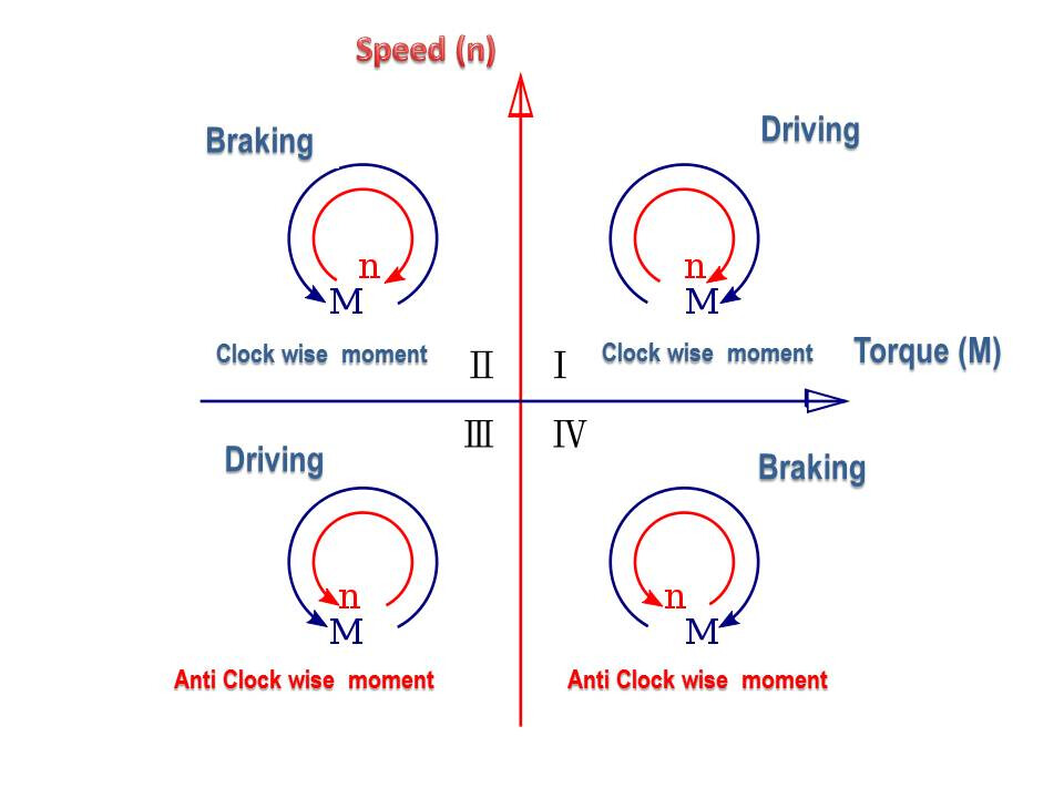
I have seen the Trajectory Control choice in the Configuration menu, and we will use this for some testing. However, there are actually three modes we need to operate in: First, actively accelerating the load (expending battery energy); second, actively decelerating the load at a rate greater than would occur by just letting the motor be braked by regen (net expenditure of battery energy); and third, actively using the motor/controller in generator-mode to recover battery energy during overall deceleration.

At this time, I am not clear as to the difference, if there is any, between the second and third mode in terms of what the H-bridges are doing, but that is a question for later.

Also, for reasons related to the way the mechanical parts interact, there is a desire to operate the controller in Torque Control mode. But that has an issue which I will question below.


For now, here are the main questions:

  1. Is there a control mode available in the GUI for setting the controller into a pure generate mode – just keep the H-bridge switching in synchrony with the rotor position to send current back up the high rail from the energy in a rotating source without ever trying to force it one way or the other?

  2. Am I correct that there is no way to actively control the motor by an external command stream through the GUI, that only pre-selected values and trajectories can be executed?

  3. In attempting to operate in Torque Control mode in the GUI, we routinely get (understandably) an error message saying the controller detected that the motor was not responding as expected and that the operation was being terminated. Since Torque Control basically just turns the controller into a current source, is there any way to make it just pump the computed current profile through the H-bridge in whatever state it happens to be at the instant, irrespective of what the encoders may be telling it about the rotation of the motor?

  4. Apparently a lot of users are able to just have the controller accelerate a load expending battery power and then, by sending a deceleration profile, put some of the stored mechanical energy back in the battery. Does the controller automatically make this phase transition seamless? (I assume that the relative phase state of the H-bridge drivers and the Hall Sensor signals reverses at that point, right?) Or is there a change of “modes” occurring?

  5. Is there a fundamental difference between how the H-bridge paths are switched (phasing relative to Hall sensors) between active deceleration operation and a pure generator operation?

I’m sorry that this post has gotten overlong, and I’m sure I’ll have other questions but I would appreciate any guidance on these questions – this mechanical system has operational characteristics that are quite different from any that I have encountered before. Thank you in advance for your responses.

Hi! Super interesting problem, thank you for the detailed overview.

First, actively accelerating the load (expending battery energy); second, actively decelerating the load at a rate greater than would occur by just letting the motor be braked by regen (net expenditure of battery energy); and third, actively using the motor/controller in generator-mode to recover battery energy during overall deceleration

Generally any deceleration of the motor by the ODrive (e.g. negative torque) will result in regeneration.

Is there a control mode available in the GUI for setting the controller into a pure generate mode – just keep the H-bridge switching in synchrony with the rotor position to send current back up the high rail from the energy in a rotating source without ever trying to force it one way or the other?

If you put it into torque mode, any torque setpoint commanded with an opposite sign as the motor rotation direction will cause regeneration (ignoring motor/ODrive/system inefficiencies) – there are no operational regimes where this is not the case.

Am I correct that there is no way to actively control the motor by an external command stream through the GUI, that only pre-selected values and trajectories can be executed?

You can have the GUI open while sending external commands over UART or CAN (inspector tab only, the dashboard tab would “fight” any external inputs). But otherwise correct.

In attempting to operate in Torque Control mode in the GUI, we routinely get (understandably) an error message saying the controller detected that the motor was not responding as expected and that the operation was being terminated. Since Torque Control basically just turns the controller into a current source, is there any way to make it just pump the computed current profile through the H-bridge in whatever state it happens to be at the instant, irrespective of what the encoders may be telling it about the rotation of the motor?

This doesn’t 100% make sense. What specific error are you getting. Do you mean a spinout error? That’s a bit different.

Apparently a lot of users are able to just have the controller accelerate a load expending battery power and then, by sending a deceleration profile, put some of the stored mechanical energy back in the battery. Does the controller automatically make this phase transition seamless? (I assume that the relative phase state of the H-bridge drivers and the Hall Sensor signals reverses at that point, right?) Or is there a change of “modes” occurring?

Yup, all seamless

Is there a fundamental difference between how the H-bridge paths are switched (phasing relative to Hall sensors) between active deceleration operation and a pure generator operation?

Nope! ODrive does direct control over the motor current, and internally there’s really no if/else on the PWM switching states, the general approach for FOC on BLDCs is very different than typical H-bridges on brushed motors (you can do something very similar with brushed motors, but nobody does haha).

I’m sorry that this post has gotten overlong, and I’m sure I’ll have other questions but I would appreciate any guidance on these questions – this mechanical system has operational characteristics that are quite different from any that I have encountered before. Thank you in advance for your responses.

I 1000% appreciate all the detail and the questions! Makes my job a lot easier.

Some questions/comments I have:

We have a large rotating mass that is externally accelerated from zero, rotates for a while, and then is externally stopped. We intend to add a small motor geared to the mass that would reduce some of the perturbations in the rotation that are introduced by the non-ideal external drive. So with respect to the load, we want to be able to accelerate it and decelerate it by small amounts.

Let me rephrase your description to make sure I understand:

  • You have some flywheel/high inertia load
  • Something externally accelerates up the flywheel
  • There’s some sort of external disturbance on the flywheel, accelerating/decelerating it semi-unpredictably
  • You want to connect an additional motor to the flywheel, powered by the ODrive Micro, that essentially just keeps it spun up at the ideal speed, providing some acceleration when speed drops and deceleration when speed increases
  • Eventually the flywheel gets spun down (due to external load? just due to the system turning off?), and you want the Micro to contribute to this spin-down and recover as much energy as possible from the flywheel.

Is this correct?

If so, I think you can just run the Micro in velocity control, with whatever velocity setpoint corresponds to the flywheel speed. It’ll brake (and regenerate) if the velocity is too high, and accelerate the motor if the velocity is too low. And then at the end of operation, you can command zero velocity, and it’ll brake the motor to zero speed while regenerating the power.

The other half is that we want to do as many upfront experiments as possible using the GUI interface before we have to dive in and learn the odrive API interface with its hundreds of commands.

Haha, understood. There’s definitely a lot of parameters, but you don’t need to know much – the GUI configuration tab really does all the setup for you, and you can use the GUI dashboard for tuning.

I think for your application, all you need to do is:

  • Set the ODrive to closed loop (assuming it’s already configured for velocity control mode) (axis0.requested_state = AxisState.CLOSED_LOOP_CONTROL)
  • Send velocity setpoints (axis0.controller.input_vel)
  • Maybe change axis0.controller.config.torque_soft_max/torque_soft_min if you want to modify the allowable motor torque
  • Maybe monitor motor current (axis0.motor.Iq_measured) and/or bus current (ibus)

Quick diagram of the motoring/generating thing – all ODrives are what’s called a “four quadrant” drive, which means that it’s able to seamlessly command both positive and negative torque no matter the motor rotation direction.

Any operation in quadrants I and III (e.g. torque sign == motor velocity sign, aka acceleration/motoring/driving) will result in power being drawn from the bus, and any operation in quadrants II and IV (torque sign opposite of motor velocity sign, aka braking) will result in power being regenerated to the bus.

Hi and thanks for the quick and detailed response. I only have a short window this afternoon but I will clarify a couple of things you mentioned.
The main mass is accelerated, “maintained”, and then decelerated by another part of the system that is outside of our control. But it exhibits kind of jerky forcing, call it “mechanical noise”, on the order of a few Hz. We’d like to damp out this noise as much as possible by having a faster actuator (our motor) add or subtract small amounts of rotational energy quickly from the main mass. However, we can’t use Velocity mode because the RPM of the main mass that we want to filter varies A LOT, like over a factor of three or four from slowest operation to fastest. So the only way to use Velocity mode is to continually sense the present average RPM’s and then continually set that as the control Velocity, using some reasonable averaging time. Call it “smart damping” and that is ultimately what we want to achieve. The reason we were encouraged to look at Torque mode is that the perturbations are SOMEWHAT repeatable over each cycle, and therefore we can plot an equivalent “perturbing torque” and try to counter it with our own “correcting torque”, and just pump that value out through our motor at a rate that’s synchronized to whatever RPM the mass is spinning at. That would allow us, for example, to have a lookup table of torque values versus rotational angle, whch would simplify the control problem, because this system has some tendencies to chaotic motion. So that’s the physical environment.

With respect to the GUI, when I was first bringing up the motor, it kept giving this error message!
image|622x499
Well that’s the first time I ever saw the word “plausible” in an error message, and I eventually determined that I was trying to be too careful and put too low a voltage on the board (supposedly the board will work down to 9 or 8V (?) but somewhere in the GUI instructions it said “be sure you’ve put at least 12V on the board” and doing that made the error message go away and calibration proceeded politely from there. But it illustrates that there are a lot of behind the curtain checks that are being done in the GUI/odrive software to make operation safe and friendly, and those sometimes kick in and prevent the operation we think we’re seeking from proceeding - like maybe it sees the rotor not responding as expected to the forcing function that it calibrated for, and thinks that’s implausible :grinning:

In any case, that’s where I’m at right now. I will do some more experimenting over the weekend and most probably will have additional questions then. Thanks very much for your help.