Hello,
I am starting a design where the encoder (CUI AMT102 2048 PPR) will be on a shaft driven by a motor with pulley/belt with a (mandatory) reduction ratio of 60/16 = 3.75.
Does it work with odrive ?
If not, any hints to make it work ?
I am new to oDrive, sorry if this is a stupid or well-known question.
I am using single shaft low cost MT4114 motor.
Placing the encoder on this shaft will be complicated and will require additional parts.
While placing it on the driven shaft will be obvious : no additional part, just screw the encoder on a plate traversed by this shaft.
I just find (very rare I think) GT2 15 teeth pulley instead of the 16T that I intended to use.
This will give a 4:1 reduction ratio.
Maybe using a 4:1 ratio instead of a 3.75 ratio will be easier to manage with oDrive. ?
The question is not about the mechanical design.
The question is about the capability for oDrive to manage an encoder placed on a driven shaft with any reduction ratio.
Is there any restrictions ?
By not an open design, I mean that I am not allowed to give any detail on the application.
The principle is very simple :
There is a small MT414 motor with a 16T pulley in a very tight enclosure (no room to add any other component on the shaft or in front of it).
From this 16T pulley, a belt drives a shaft with a 60T pulley on it.
The reduction ratio between the motor and this shaft is 60/15 = 3.75.
(This is equivalent to a geared motor with a 3.75 reduction ratio)
The only possibility is to place the encoder on this shaft.
That’s all I can explain.
Can I use oDrive in a system where the motor rotates at 3.75 times the speed of the encoder ?
On principale I don’t see why it wouldn’t work.
Just introduce your gear reduction ratio on odrv0.axis0.encoder.config.cpr and that’s it I guess.
Warning: I never tried myself.
Second warning: you should really severely torture test your setup before actually using it.
Because when the mechanical connection is lost between the encoder and motor movements, thing can go super wrong. That’s why i would keep the encoder as close as possible from the motor shaft. Since you’re not allowed to share details, I would be even more careful (in other words I wouldn’t do it)
In any case ( if all goes well ), I will do it and test it.
I will make the design compatible with a 3.75 and 4 reduction ratio.
By now, I am not sure that the latest version of oDrive will accept a floating point value for the reduction ratio in odrv0.axis0.encoder.config.cpr. (I still need to get a board or dig into the firmware).
Note : in my case, if the mechanical connection is lost between the motor and the encoder nothing wrong can happen except crazy rotations of the motor which is not a safety issue.
In this particular design, the driven shaft is only moving +90° to -90°, meaning less than two revolutions for the motor with a 4:1 reduction ratio.
In this case, I will need to modify the firmware to let the motor rotate for two rotations until reaching the cpr value.
or to choose another option than oDrive (e.g. stepper motor) if this does not work.
Sorry not to give more details, but that’s out of my control.
Hi @jct, your question was clear from your first post, and it’s a great question.
The simple way would be to scale your cpr from 8192 (= ppr x4), to a new effective value. However, as you guessed, this must be an integer. In your case:
8192/3.75 = 2184.53333333
So that doesn’t work.
We have more options though. We can scale the pole-pairs and the effective cpr together. You can imagine that we form a virtual motor where we go around the physical motor twice, and we say that’s one virtual turn. In that case we scale the pole-pairs and the cpr up by factor two.
In fact, we can scale both together by any factor, as long as the resulting pole-pairs and cpr are both integers.
k * cpr_{effective} = cpr_{scaled} = \text{Integer}
k * pp = pp_{scaled} = \text{Integer}
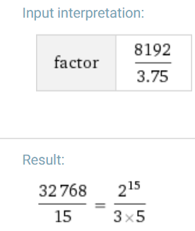
I asked Wolfram Alpha to find the factors of your effective CPR, and it found this:
Therefore, i think you can use k = 15, and hence set your scaled CPR to 32769, and your scaled pole pairs to the physical pole pairs times 15.
After reviewing the overall design and taking into account that in fact GT2 15T/60T pulleys are readily available from some providers, I will use the 4:1 gear ratio.
In any case, it is very useful to know that other ratios are possible.
Sorry to revive this old thread, but I think this element that I want to discuss may be interesting not just to me in the context of this overall topic.
The concept of placing the encoder further along a transmission chain (away from the motor) is interesting because it places the position feedback closer to the final element or end effector, which is where we would most of the time wish to have the most certainty in positioning. We can already see however that backlash would in many cases lead to problematic behavior of the system.
If we assume an ideal, backlash-free speed-reducing transmission with a total reduction ratio that is an integer to properly multiply the polepairs for the ODrive to be able to commutate the motor normally, there would theoretically be no problems. However, no transmission is perfect and while we may be able to achieve a zero-backlash system, we may not be able to achieve a perfect scale-down of cyclic motion or velocity profile. In other words, there may be some unevenness in the elements of the transmission that leads to waviness in motion profile, causing motor commutation (magnetic sequence) and encoder counts to not always be in the same sync and ratio.
One illustrative example is this: We construct a single-stage roller chain speed-reduction transmission with a small chain sprocket directly attached to the motor and a large chain sprocket attached to the rotating end effector, where the encoder is mounted. We then mount a second, identical sprocket next to each respective sprocket of the transmission and use two identical chains and construct the sprocket hubs in such a way that the second (parallel) path’s sprockets can be rotationally offset in such a way that any backlash is taken out of the system by preloading the chains against each other and letting elastic averaging and chain tensioning do the rest (mechanical design needs to have purposefully chosen compliance characteristics in all elements, I do not necessarily recommend this sort of design but it illustrates the point).
If we consider the backlash to now be eliminated, we still encounter a problem: Roller chains exhibit a characteristic called chordal action or ‘polygon effect’ that leads to a (cyclic) acceleration and deceleration as one sprocket tooth is advanced. The roller chain is not a constant velocity system.
The question is now how much error the ODrive is able to tolerate when it comes to this sort of “wow and flutter” difference between magnetic phase sequence and encoder pulse feedback. This problem may actually to a certain extent be comparable to a poorly constructed motor.
Any thoughts on this are greatly appreciated.
I think it is interesting too as I have no idea if a PID is able to correct for hysterese / backlash error “down the line” or that it would require additional feed forward?
I don’t think that elasticity or unbalance is a problem, though and PID should work: the Odrive does not try to keep the rotation of the motor aligned it is sending currents to the motor to try and get it to move to the right encoder position, not rotor position.
But then I just ordered my Odrive and have to digg into the software that’s running on it
As long as the polygon effect means that the peak error of motor position (as seen by the encoder) is 15 degrees electrical or less, the commutation should be okay.
What does “Okay” mean in this context? Is there an impact on efficiency / torque production?
I’ve never heard of the “polygon effect” in the context of field-oriented control of motors before. I can only find it in the context of gears and chain-sprocket wheels. What is it?
I suppose the drive is doing a linear interpolation along a discretely sampled sinus, and that’s what you mean by polygon effect?