Error of current_limit_violation

hello community,
i have odrive v3.6 of 56v which controls two same motors . well,I am giving both the motors same configurations but still when i give
odrv0.axis0.controller.input_pos = 10 and then 0 alternately
I am getting error of current limit violation in the motor at axis0 . well I tried to increase current control bandwidth and current limit but it was in vain.I also exchanged the axis and motors but then also I am getting current limit violation error

here I have mentioned all the details regarding to it

configurations :-
odrv0.axis0.motor.config.current_lim = 30
odrv0.axis0.motor.config.current_lim_margin = 20
odrv0.axis0.motor.config.calibration_current = 8
odrv0.axis0.motor.config.current_control_bandwidth =2500
odrv0.axis0.encoder.config.cpr = 8192
odrv0.axis0.motor.config.pole_pairs =7

odrv0.axis0.controller.config.vel_limit_tolerance=5
odrv0.axis0.controller.config.vel_limit = 50

odrv0.axis0.controller.config.pos_gain = 40.0
odrv0.axis0.controller.config.vel_gain = 0.2
odrv0.axis0.controller.config.vel_integrator_gain = 1

odrv0.axis0.controller.config.input_mode = InputMode.TRAP_TRAJ
odrv0.axis0.trap_traj.config.vel_limit = 40
odrv0.axis0.trap_traj.config.accel_limit = 50
odrv0.axis0.trap_traj.config.decel_limit = 50

odrv0.axis0.motor.config.resistance_calib_max_voltage = 10 #(phase inductance out of range)
odrv0.axis0.controller.config.spinout_electrical_power_threshold = 1000
odrv0.axis0.controller.config.spinout_mechanical_power_threshold = -1000

odrv0.config.enable_brake_resistor = True
odrv0.config.brake_resistance = 2

uart configuration

odrv0.config.enable_uart_a = True
odrv0.config.gpio1_mode = GpioMode.UART_A
odrv0.config.gpio2_mode = GpioMode.UART_A


odrv0.axis1.motor.config.current_lim = 30
odrv0.axis1.motor.config.current_lim_margin = 20
odrv0.axis1.motor.config.calibration_current = 8
odrv0.axis1.motor.config.current_control_bandwidth =2500
odrv0.axis1.encoder.config.cpr = 8192
odrv0.axis1.motor.config.pole_pairs =7

odrv0.axis1.controller.config.vel_limit_tolerance=5
odrv0.axis1.controller.config.vel_limit = 50

odrv0.axis1.controller.config.pos_gain = 40.0
odrv0.axis1.controller.config.vel_gain = 0.2
odrv0.axis1.controller.config.vel_integrator_gain = 1

odrv0.axis1.controller.config.input_mode = InputMode.TRAP_TRAJ
odrv0.axis1.trap_traj.config.vel_limit = 40
odrv0.axis1.trap_traj.config.accel_limit = 50
odrv0.axis1.trap_traj.config.decel_limit = 50

odrv0.axis1.motor.config.resistance_calib_max_voltage = 10 #(phase inductance out of range)
odrv0.axis1.controller.config.spinout_electrical_power_threshold = 1000
odrv0.axis1.controller.config.spinout_mechanical_power_threshold = -1000

odrv0.config.enable_brake_resistor = True
odrv0.config.brake_resistance = 2#(2 for odesc and 0.5 for odrive)

uart configuration

odrv0.config.enable_uart_a = True
odrv0.config.gpio1_mode = GpioMode.UART_A
odrv0.config.gpio2_mode = GpioMode.UART_A

here are the phase resistance and inductance calculated for it
#phase resistance
axis0 0.07148325443267822
axis1 0.07039767503738403
#phase inductance
axis0 3.077850124100223e-05
axis1 4.213920692563988e-05


motor :-
maytech MTO5055-HA

encoder :-
cui amt 102


thanks :blush:

Hi! Does it still happen if you make the trap traj accel and decel values smaller? It’s likely accelerating too quickly and either losing control or the encoder is slipping on the shaft

yes, I tried to lower the values but it is still happening and I am sure that the encoder is not slipping because I have kept the arrangement of the motor such that it won’t slip encoder

please can anyone help me with these as i am still persisting the same problem .is it possible that this is problem in odrive v3.6 only and not in odrive pro/s1 as odrive v3.6 is old

What ODrive firmware version are you using? And was this ODrive purchased from our store or from somewhere else?

the firmware version of odrive is v0.5.5 and it was purchased through shop from odrive

What’s your odrv0.axis0.motor.config.requested_current_range ?

the requested current range is 60

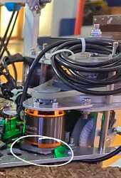
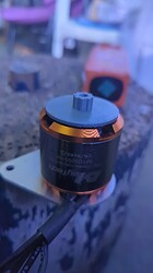
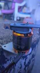
Can you send some pictures of how the encoder is mounted, showing the encoder mounting and the motor shaft going through the encoder? An image from the side would also be helpful. If you reduce the spinout_electrical_power_threshold to 20 and spinout_mechanical_power_threshold to -20, does it give a spinout error instead of a current limit violation error?


  • First one shows the current setup where I’m facing the error.
  • The second and third are just for reference, showing different parts I used to build the structure. They should help clarify how everything fits together.

and for spinout ,well i was getting spinout error like, motor was loosing control automatically while i was driving my robot, therefore i had to increase it and after doing that i never re-encoutered the same problem

Okay, so this is definitely an encoder issue if you were getting the spinout errors before. By increasing the spinout thresholds, the error was masked until it turned into a current control issue. A few questions:

  • What is holding that gray 3D printed piece onto the motor? Is it glued? Just a friction fit?
  • Are you using the correct shaft sleeve with the encoder, or is the gray spline directly interfacing with the encoder rotor?
  • When you calibrate the robot, is it done with zero load and the motor belt disconnected? Are you using index search?

the gray 3D printed piece onto the motor is friction fit like it has 3d printed extrusion which goes inside the hole and it is printed in specific manner that it does not touch the internal circuit of motor .
i am using the gray spline for direct interfacing with the encoder rotor an it is positively engaged with it so according to me it must not be the problem
when i calibrate the motor i am doing it with zero load and also motor belt disconnected. I am not using encoder index search rather than i am using encoder offset callibration

Hmm, I’d definitely blame the 3D printed piece here. Any eccentricity or runout can cause an issue, and spinout typically indicates it’s an encoder issue. As well, the CUI encoders really want to be mounted a consistent distance from the motor, or they can have issues. What’s your axis0.config.calibration_lockin.current set to?

the axis0.config.calibration_lockin.currentis set to 10 and what must be consistent distance between cui encoder and motor ?

You should follow the AMT102 installation instruction manual: https://www.sameskydevices.com/product/resource/amt10.pdf. You can try increasing the calibration_lockin.current to your motor’s continuous current limit.