ESP32 CAN control ODrive Pro Example

I am struggling with getting CAN working on ODrive. In my present config we have an ESP32 with a CAN Transceiver.

Motor is configured and we have control over the GUI. It’s allegedly configured for heartbeats and CAN ID 3.
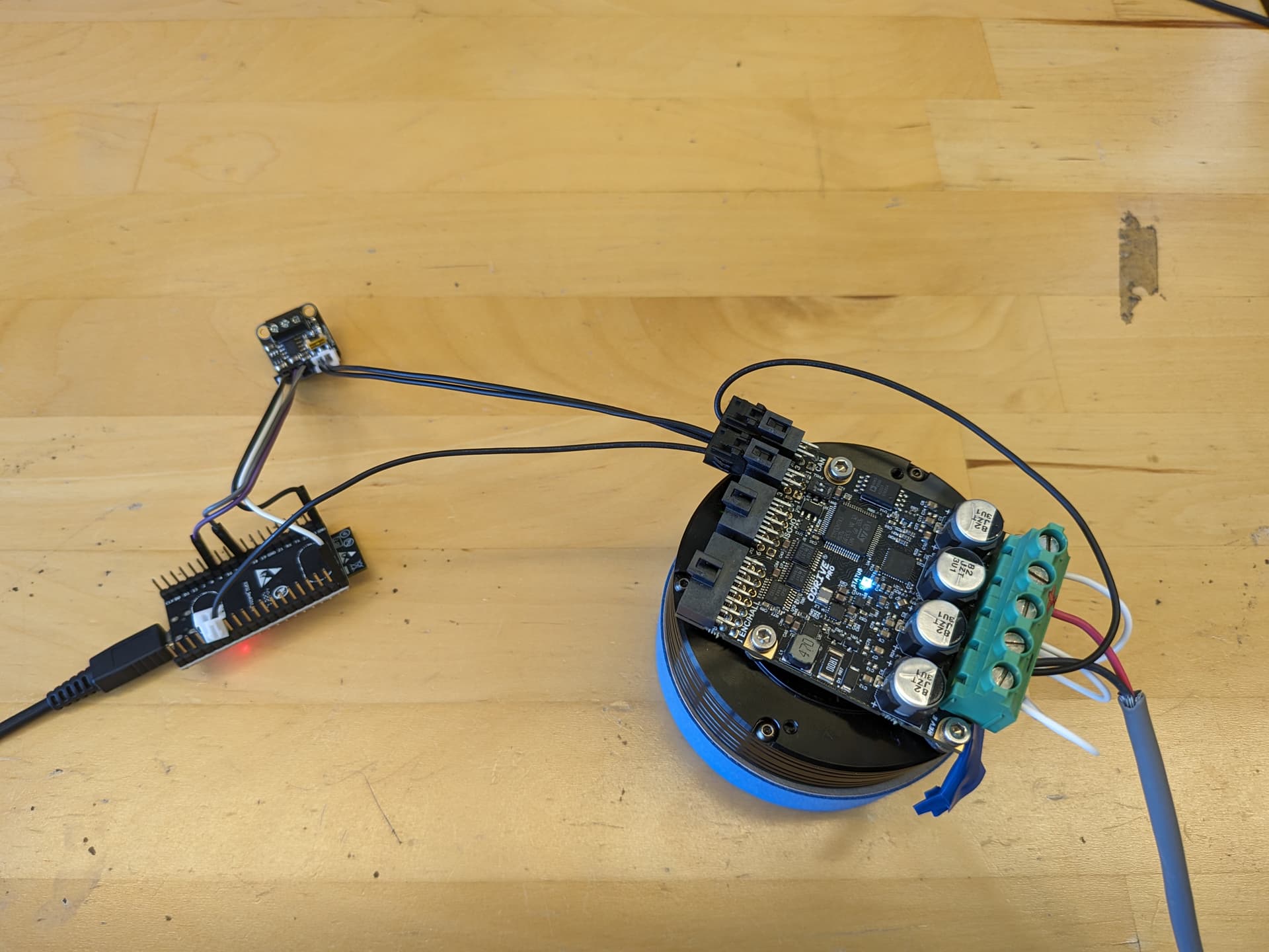
Our setup:

We tried 2 approaches.

  1. Sending CAN commands directly.
  2. Making a custom wrapper to get the example to work.

Neither works. This post is about approach 2, Approach 1 is covered by this post.

My version of the example edited to include ESP32 as an option. (The “any microcontroller with an MCP2515” option doesn’t work for us either as it fails to compile as soon as you select an esp32 bootloader). So, the edited example here with our code from 143-174

#include <Arduino.h>
#include "ODriveCAN.h"

// Documentation for this example can be found here:
// https://docs.odriverobotics.com/v/latest/guides/arduino-can-guide.html


/* Configuration of example sketch -------------------------------------------*/

// CAN bus baudrate. Make sure this matches for every device on the bus
#define CAN_BAUDRATE 500000

// ODrive node_id for odrv0
#define ODRV0_NODE_ID 3

// Uncomment below the line that corresponds to your hardware.
// See also "Board-specific settings" to adapt the details for your hardware setup.

// #define IS_TEENSY_BUILTIN // Teensy boards with built-in CAN interface (e.g. Teensy 4.1). See below to select which interface to use.
// #define IS_ARDUINO_BUILTIN // Arduino boards with built-in CAN interface (e.g. Arduino Uno R4 Minima)
// #define IS_MCP2515 // Any board with external MCP2515 based extension module. See below to configure the module.
#define IS_ESP32

/* Board-specific includes ---------------------------------------------------*/

#if defined(IS_TEENSY_BUILTIN) + defined(IS_ARDUINO_BUILTIN) + defined(IS_MCP2515) + defined(IS_ESP32)!= 1
#warning "Select exactly one hardware option at the top of this file."

#if CAN_HOWMANY > 0 || CANFD_HOWMANY > 0
#define IS_ARDUINO_BUILTIN
#warning "guessing that this uses HardwareCAN"
#else
#error "cannot guess hardware version"
#endif

#endif

#ifdef IS_ARDUINO_BUILTIN
// See https://github.com/arduino/ArduinoCore-API/blob/master/api/HardwareCAN.h
// and https://github.com/arduino/ArduinoCore-renesas/tree/main/libraries/Arduino_CAN

#include <Arduino_CAN.h>
#include <ODriveHardwareCAN.hpp>
#endif // IS_ARDUINO_BUILTIN

#ifdef IS_MCP2515
// See https://github.com/sandeepmistry/arduino-CAN/
#include "MCP2515.h"
#include "ODriveMCPCAN.hpp"
#endif // IS_MCP2515

#ifdef IS_TEENSY_BUILTIN
// See https://github.com/tonton81/FlexCAN_T4
// clone https://github.com/tonton81/FlexCAN_T4.git into /src
#include <FlexCAN_T4.h>
#include "ODriveFlexCAN.hpp"
struct ODriveStatus; // hack to prevent teensy compile error
#endif // IS_TEENSY_BUILTIN

#ifdef IS_ESP32
#include <CAN.h>
#include "ODriveESP32.hpp"
#endif //IS_ESP32


/* Board-specific settings ---------------------------------------------------*/


/* Teensy */

#ifdef IS_TEENSY_BUILTIN

FlexCAN_T4<CAN1, RX_SIZE_256, TX_SIZE_16> can_intf;

bool setupCan() {
  can_intf.begin();
  can_intf.setBaudRate(CAN_BAUDRATE);
  can_intf.setMaxMB(16);
  can_intf.enableFIFO();
  can_intf.enableFIFOInterrupt();
  can_intf.onReceive(onCanMessage);
  return true;
}

#endif // IS_TEENSY_BUILTIN


/* MCP2515-based extension modules -*/

#ifdef IS_MCP2515

MCP2515Class& can_intf = CAN;

// chip select pin used for the MCP2515
#define MCP2515_CS 10

// interrupt pin used for the MCP2515
// NOTE: not all Arduino pins are interruptable, check the documentation for your board!
#define MCP2515_INT 2

// freqeuncy of the crystal oscillator on the MCP2515 breakout board. 
// common values are: 16 MHz, 12 MHz, 8 MHz
#define MCP2515_CLK_HZ 8000000


static inline void receiveCallback(int packet_size) {
  if (packet_size > 8) {
    return; // not supported
  }
  CanMsg msg = {.id = (unsigned int)CAN.packetId(), .len = (uint8_t)packet_size};
  CAN.readBytes(msg.buffer, packet_size);
  onCanMessage(msg);
}

bool setupCan() {
  // configure and initialize the CAN bus interface
  CAN.setPins(MCP2515_CS, MCP2515_INT);
  CAN.setClockFrequency(MCP2515_CLK_HZ);
  if (!CAN.begin(CAN_BAUDRATE)) {
    return false;
  }

  CAN.onReceive(receiveCallback);
  return true;
}

#endif // IS_MCP2515


/* Arduinos with built-in CAN */

#ifdef IS_ARDUINO_BUILTIN

HardwareCAN& can_intf = CAN;

bool setupCan() {
  return can_intf.begin((CanBitRate)CAN_BAUDRATE);
}

#endif


#ifdef IS_ESP32
ESP32SJA1000Class& can_intf = CAN;

// chip select pin used for the MCP2515
#define RX_PIN 4

// interrupt pin used for the MCP2515
// NOTE: not all Arduino pins are interruptable, check the documentation for your board!
#define TX_PIN 5


static inline void receiveCallback(int packet_size) {
  if (packet_size > 8) {
    return; // not supported
  }
  CanMsg msg = {.id = (unsigned int)CAN.packetId(), .len = (uint8_t)packet_size};
  CAN.readBytes(msg.buffer, packet_size);
  onCanMessage(msg);
}

bool setupCan() {
  // configure and initialize the CAN bus interface
  CAN.setPins(RX_PIN, TX_PIN);
  if (!CAN.begin(CAN_BAUDRATE)) {
    return false;
  }

  CAN.onReceive(receiveCallback);
  return true;
}

#endif


/* Example sketch ------------------------------------------------------------*/

// Instantiate ODrive objects
ODriveCAN odrv0(wrap_can_intf(can_intf), ODRV0_NODE_ID); // Standard CAN message ID
ODriveCAN* odrives[] = {&odrv0}; // Make sure all ODriveCAN instances are accounted for here

struct ODriveUserData {
  Heartbeat_msg_t last_heartbeat;
  bool received_heartbeat = false;
  Get_Encoder_Estimates_msg_t last_feedback;
  bool received_feedback = false;
};

// Keep some application-specific user data for every ODrive.
ODriveUserData odrv0_user_data;

// Called every time a Heartbeat message arrives from the ODrive
void onHeartbeat(Heartbeat_msg_t& msg, void* user_data) {
  ODriveUserData* odrv_user_data = static_cast<ODriveUserData*>(user_data);
  odrv_user_data->last_heartbeat = msg;
  odrv_user_data->received_heartbeat = true;
}

// Called every time a feedback message arrives from the ODrive
void onFeedback(Get_Encoder_Estimates_msg_t& msg, void* user_data) {
  ODriveUserData* odrv_user_data = static_cast<ODriveUserData*>(user_data);
  odrv_user_data->last_feedback = msg;
  odrv_user_data->received_feedback = true;
}

// Called for every message that arrives on the CAN bus
void onCanMessage(const CanMsg& msg) {
  for (auto odrive: odrives) {
    onReceive(msg, *odrive);
  }
}

void setup() {
  Serial.begin(115200);

  // Wait for up to 3 seconds for the serial port to be opened on the PC side.
  // If no PC connects, continue anyway.
  for (int i = 0; i < 30 && !Serial; ++i) {
    delay(100);
  }
  delay(200);


  Serial.println("Starting ODriveCAN demo");

  // Register callbacks for the heartbeat and encoder feedback messages
  odrv0.onFeedback(onFeedback, &odrv0_user_data);
  odrv0.onStatus(onHeartbeat, &odrv0_user_data);

  // Configure and initialize the CAN bus interface. This function depends on
  // your hardware and the CAN stack that you're using.
  Serial.println("Starting CAN bus");
  
  if (!setupCan()) {
    Serial.println("CAN failed to initialize: reset required");
    while (true); // spin indefinitely
  }

  Serial.println("Waiting for ODrive...");
  while (!odrv0_user_data.received_heartbeat) {
    pumpEvents(can_intf);
    delay(100);
  }

  Serial.println("found ODrive");

  // request bus voltage and current (1sec timeout)
  Serial.println("attempting to read bus voltage and current");
  Get_Bus_Voltage_Current_msg_t vbus;
  if (!odrv0.request(vbus, 1)) {
    Serial.println("vbus request failed!");
    while (true); // spin indefinitely
  }

  Serial.print("DC voltage [V]: ");
  Serial.println(vbus.Bus_Voltage);
  Serial.print("DC current [A]: ");
  Serial.println(vbus.Bus_Current);

  Serial.println("Enabling closed loop control...");
  while (odrv0_user_data.last_heartbeat.Axis_State != ODriveAxisState::AXIS_STATE_CLOSED_LOOP_CONTROL) {
    odrv0.clearErrors();
    delay(1);
    odrv0.setState(ODriveAxisState::AXIS_STATE_CLOSED_LOOP_CONTROL);

    // Pump events for 150ms. This delay is needed for two reasons;
    // 1. If there is an error condition, such as missing DC power, the ODrive might
    //    briefly attempt to enter CLOSED_LOOP_CONTROL state, so we can't rely
    //    on the first heartbeat response, so we want to receive at least two
    //    heartbeats (100ms default interval).
    // 2. If the bus is congested, the setState command won't get through
    //    immediately but can be delayed.
    for (int i = 0; i < 15; ++i) {
      delay(10);
      pumpEvents(can_intf);
    }
  }

  Serial.println("ODrive running!");
}

void loop() {
  pumpEvents(can_intf); // This is required on some platforms to handle incoming feedback CAN messages

  float SINE_PERIOD = 2.0f; // Period of the position command sine wave in seconds

  float t = 0.001 * millis();
  
  float phase = t * (TWO_PI / SINE_PERIOD);

  odrv0.setPosition(
    sin(phase), // position
    cos(phase) * (TWO_PI / SINE_PERIOD) // velocity feedforward (optional)
  );

  // print position and velocity for Serial Plotter
  if (odrv0_user_data.received_feedback) {
    Get_Encoder_Estimates_msg_t feedback = odrv0_user_data.last_feedback;
    odrv0_user_data.received_feedback = false;
    Serial.print("odrv0-pos:");
    Serial.print(feedback.Pos_Estimate);
    Serial.print(",");
    Serial.print("odrv0-vel:");
    Serial.println(feedback.Vel_Estimate);
  }
}

A wrapper is needed then that we created called, “ODriveESP32.hpp” that is located in the ODrive libraries folder:

#pragma once

#include "ESP32SJA1000.h"
#include "ODriveCAN.h"

// This is a convenience struct because the MCP2515 library doesn't have a
// native message type.
struct CanMsg {
    uint32_t id;
    uint8_t len;
    uint8_t buffer[8];
};

// Must be defined by the application if you want to use defaultCanReceiveCallback().
void onCanMessage(const CanMsg& msg);

static bool sendMsg(ESP32SJA1000Class& can_intf, uint32_t id, uint8_t length, const uint8_t* data) {
    if (id & 0x80000000) {
        can_intf.beginExtendedPacket(id & 0x1fffffff, length, !data);
    } else {
        can_intf.beginPacket(id, length, !data);
    }
    if (data) {
        for (int i = 0; i < length; ++i) {
            can_intf.write(data[i]);
        }
    }
    return can_intf.endPacket();
}

static void onReceive(const CanMsg& msg, ODriveCAN& odrive) {
    odrive.onReceive(msg.id, msg.len, msg.buffer);
}

static void pumpEvents(ESP32SJA1000Class& intf) {
    // nothing to do
    // TODO: maybe remove
    delay(10); // not sure why this resulted in less dropped messages, could have been a twisted coincidence
}

CREATE_CAN_INTF_WRAPPER(ESP32SJA1000Class)

It is heavily inspired by the “ODriveMCPCAN.hpp” wrapper included in the ODrive libraries.

I might be able to help you a bit here. We used can with esp32 for a long time now and i was thinking about implementing an odrive can interface as well.

First off, Esp32 doesnt support the mcp2515 ic’s at all. It does however support the mcp26 and the texas instruments sn65hvd2xx ic’s. We use the latter; but most ic’s in this family are fine. Dont connect the grounds due to ground loops. And finally, keep in mind to use the real TI’s and not the SID knockoffs, we found that they are totally different beasts.

CAN also requires proper termination and proper cabling. The TI datasheets are quite good on these details. I can recommend standard cat5 cables; use one twisted pair and wire the rest on one end to the chassis (earth, not gnd).

I dunno about the baud rate that odrive uses. Esp32 supports the 1 mbit max protocol and calls it TWAI.

Finally, personally i would try to use the esp-idf api instead of the arduino api because it is much easier to debug and usually gives way more information.

If you have new code, please do post it since i think about venturing into this odrive/can thing to avoid ground loops as well.

Take a look at this repo odrive_can_functions/pc104_controller/src/odrive_can_functions.cpp at control · chinacat567/odrive_can_functions · GitHub it does an ok job of showing how to construct and parse CAN messages.

Use Can-utils - eLinux.org, specifically candump to ensure you’re seeing the heartbeat message; that will remove the variable of your own software having bugs. If that works, then start debugging your software.

Hi @Robot_Nerd,

Did you make any progress with this I am working through the exact same issue now.

EDIT:
I ran the above code and adjusted my TX RX pins and it worked first go! I am using the Adafruit CAN PAL

Hello @Lewis_miles. Yes, I got ODrive Pro working with ESP32’s. I hate dead forum posts with good questions… so I’ll share my process below, maybe it can help you or anyone else.

First quick summary of my issue? CAN can be measured as “there” or “there and back”. And your libraries definition and ODrive’s definition aren’t necessarily the same. Everything works for me when ODrives are set to 500k and the CAN objects in your code are set to 1,000k…

To make sure we have similar hardware first… This is my setup:

The Esp32 has a native CAN peripheral support… so you don’t need a full on CAN device like the MCP burning all your pin slots. All you should need in theory is a transceiver So why is that so much harder to get working?! Well… now it’s not, good luck out there.

So onto how to get ESP32 working with your ODrive!

  1. You need a new wrapper located in your library. If you are in Arduino, that’s Arduino/libraries/ODriveArduino/src.
    I called it ODriveESP32.hpp. I’m not even sure what most of it does, but apparently I did a good enough job because it works bug free (well, haha no bugs from the CAN interface anyway).
#pragma once

#include "ESP32SJA1000.h"
#include "ODriveCAN.h"

// This is a convenience struct because the MCP2515 library doesn't have a
// native message type.
struct CanMsg {
    uint32_t id;
    uint8_t len;
    uint8_t buffer[8];
};

// Must be defined by the application if you want to use defaultCanReceiveCallback().
void onCanMessage(const CanMsg& msg);

static bool sendMsg(ESP32SJA1000Class& can_intf, uint32_t id, uint8_t length, const uint8_t* data) {
    if (id & 0x80000000) {
        can_intf.beginExtendedPacket(id & 0x1fffffff, length, !data);
    } else {
        can_intf.beginPacket(id, length, !data);
    }
    if (data) {
        for (int i = 0; i < length; ++i) {
            can_intf.write(data[i]);
        }
    }
    return can_intf.endPacket();
}

static void onReceive(const CanMsg& msg, ODriveCAN& odrive) {
    odrive.onReceive(msg.id, msg.len, msg.buffer);
}

static void pumpEvents(ESP32SJA1000Class& intf) {
    // nothing to do
    // TODO: maybe remove
    delay(10); // not sure why this resulted in less dropped messages, could have been a twisted coincidence
}

CREATE_CAN_INTF_WRAPPER(ESP32SJA1000Class)
  1. Set your ODrive Pro up with your motor and calibrate it using CAN for comms at 500.

  2. I don’t know how to write your code for you, but here is the example they provided that works with an ESP32 if you added the wrapper I told you.

#include <Arduino.h>
#include "ODriveCAN.h"

// Documentation for this example can be found here:
// https://docs.odriverobotics.com/v/latest/guides/arduino-can-guide.html


/* Configuration of example sketch -------------------------------------------*/

// CAN bus baudrate. Make sure this matches for every device on the bus
#define CAN_BAUDRATE 1000000

// ODrive node_id for odrv0
#define ODRV0_NODE_ID 3

// Uncomment below the line that corresponds to your hardware.
// See also "Board-specific settings" to adapt the details for your hardware setup.

// #define IS_TEENSY_BUILTIN // Teensy boards with built-in CAN interface (e.g. Teensy 4.1). See below to select which interface to use.
// #define IS_ARDUINO_BUILTIN // Arduino boards with built-in CAN interface (e.g. Arduino Uno R4 Minima)
// #define IS_MCP2515 // Any board with external MCP2515 based extension module. See below to configure the module.
#define IS_ESP32

/* Board-specific includes ---------------------------------------------------*/

#if defined(IS_TEENSY_BUILTIN) + defined(IS_ARDUINO_BUILTIN) + defined(IS_MCP2515) + defined(IS_ESP32)!= 1
#warning "Select exactly one hardware option at the top of this file."

#if CAN_HOWMANY > 0 || CANFD_HOWMANY > 0
#define IS_ARDUINO_BUILTIN
#warning "guessing that this uses HardwareCAN"
#else
#error "cannot guess hardware version"
#endif

#endif

#ifdef IS_ARDUINO_BUILTIN
// See https://github.com/arduino/ArduinoCore-API/blob/master/api/HardwareCAN.h
// and https://github.com/arduino/ArduinoCore-renesas/tree/main/libraries/Arduino_CAN

#include <Arduino_CAN.h>
#include <ODriveHardwareCAN.hpp>
#endif // IS_ARDUINO_BUILTIN

#ifdef IS_MCP2515
// See https://github.com/sandeepmistry/arduino-CAN/
#include "MCP2515.h"
#include "ODriveMCPCAN.hpp"
#endif // IS_MCP2515

#ifdef IS_TEENSY_BUILTIN
// See https://github.com/tonton81/FlexCAN_T4
// clone https://github.com/tonton81/FlexCAN_T4.git into /src
#include <FlexCAN_T4.h>
#include "ODriveFlexCAN.hpp"
struct ODriveStatus; // hack to prevent teensy compile error
#endif // IS_TEENSY_BUILTIN

#ifdef IS_ESP32
#include <CAN.h>
#include "ODriveESP32.hpp"
#endif //IS_ESP32


/* Board-specific settings ---------------------------------------------------*/


/* Teensy */

#ifdef IS_TEENSY_BUILTIN

FlexCAN_T4<CAN1, RX_SIZE_256, TX_SIZE_16> can_intf;

bool setupCan() {
  can_intf.begin();
  can_intf.setBaudRate(CAN_BAUDRATE);
  can_intf.setMaxMB(16);
  can_intf.enableFIFO();
  can_intf.enableFIFOInterrupt();
  can_intf.onReceive(onCanMessage);
  return true;
}

#endif // IS_TEENSY_BUILTIN


/* MCP2515-based extension modules -*/

#ifdef IS_MCP2515

MCP2515Class& can_intf = CAN;

// chip select pin used for the MCP2515
#define MCP2515_CS 10

// interrupt pin used for the MCP2515
// NOTE: not all Arduino pins are interruptable, check the documentation for your board!
#define MCP2515_INT 2

// freqeuncy of the crystal oscillator on the MCP2515 breakout board. 
// common values are: 16 MHz, 12 MHz, 8 MHz
#define MCP2515_CLK_HZ 8000000


static inline void receiveCallback(int packet_size) {
  if (packet_size > 8) {
    return; // not supported
  }
  CanMsg msg = {.id = (unsigned int)CAN.packetId(), .len = (uint8_t)packet_size};
  CAN.readBytes(msg.buffer, packet_size);
  onCanMessage(msg);
}

bool setupCan() {
  // configure and initialize the CAN bus interface
  CAN.setPins(MCP2515_CS, MCP2515_INT);
  CAN.setClockFrequency(MCP2515_CLK_HZ);
  if (!CAN.begin(CAN_BAUDRATE)) {
    return false;
  }

  CAN.onReceive(receiveCallback);
  return true;
}

#endif // IS_MCP2515


/* Arduinos with built-in CAN */

#ifdef IS_ARDUINO_BUILTIN

HardwareCAN& can_intf = CAN;

bool setupCan() {
  return can_intf.begin((CanBitRate)CAN_BAUDRATE);
}

#endif


#ifdef IS_ESP32
ESP32SJA1000Class& can_intf = CAN;

// chip select pin used for the MCP2515
#define RX_PIN 4

// interrupt pin used for the MCP2515
// NOTE: not all Arduino pins are interruptable, check the documentation for your board!
#define TX_PIN 5


static inline void receiveCallback(int packet_size) {
  if (packet_size > 8) {
    return; // not supported
  }
  CanMsg msg = {.id = (unsigned int)CAN.packetId(), .len = (uint8_t)packet_size};
  CAN.readBytes(msg.buffer, packet_size);
  onCanMessage(msg);
}

bool setupCan() {
  // configure and initialize the CAN bus interface
  CAN.setPins(RX_PIN, TX_PIN);
  if (!CAN.begin(CAN_BAUDRATE)) {
    return false;
  }

  CAN.onReceive(receiveCallback);
  return true;
}

#endif


/* Example sketch ------------------------------------------------------------*/

// Instantiate ODrive objects
ODriveCAN odrv0(wrap_can_intf(can_intf), ODRV0_NODE_ID); // Standard CAN message ID
ODriveCAN* odrives[] = {&odrv0}; // Make sure all ODriveCAN instances are accounted for here

struct ODriveUserData {
  Heartbeat_msg_t last_heartbeat;
  bool received_heartbeat = false;
  Get_Encoder_Estimates_msg_t last_feedback;
  bool received_feedback = false;
};

// Keep some application-specific user data for every ODrive.
ODriveUserData odrv0_user_data;

// Called every time a Heartbeat message arrives from the ODrive
void onHeartbeat(Heartbeat_msg_t& msg, void* user_data) {
  ODriveUserData* odrv_user_data = static_cast<ODriveUserData*>(user_data);
  odrv_user_data->last_heartbeat = msg;
  odrv_user_data->received_heartbeat = true;
}

// Called every time a feedback message arrives from the ODrive
void onFeedback(Get_Encoder_Estimates_msg_t& msg, void* user_data) {
  ODriveUserData* odrv_user_data = static_cast<ODriveUserData*>(user_data);
  odrv_user_data->last_feedback = msg;
  odrv_user_data->received_feedback = true;
}

// Called for every message that arrives on the CAN bus
void onCanMessage(const CanMsg& msg) {
  for (auto odrive: odrives) {
    onReceive(msg, *odrive);
  }
}

void setup() {
  Serial.begin(115200);

  // Wait for up to 3 seconds for the serial port to be opened on the PC side.
  // If no PC connects, continue anyway.
  for (int i = 0; i < 30 && !Serial; ++i) {
    delay(100);
  }
  delay(200);


  Serial.println("Starting ODriveCAN demo");

  // Register callbacks for the heartbeat and encoder feedback messages
  odrv0.onFeedback(onFeedback, &odrv0_user_data);
  odrv0.onStatus(onHeartbeat, &odrv0_user_data);

  // Configure and initialize the CAN bus interface. This function depends on
  // your hardware and the CAN stack that you're using.
  Serial.println("Starting CAN bus");
  
  if (!setupCan()) {
    Serial.println("CAN failed to initialize: reset required");
    while (true); // spin indefinitely
  }

  Serial.println("Waiting for ODrive...");
  while (!odrv0_user_data.received_heartbeat) {
    pumpEvents(can_intf);
    delay(100);
  }

  Serial.println("found ODrive");

  // request bus voltage and current (1sec timeout)
  Serial.println("attempting to read bus voltage and current");
  Get_Bus_Voltage_Current_msg_t vbus;
  if (!odrv0.request(vbus, 1)) {
    Serial.println("vbus request failed!");
    while (true); // spin indefinitely
  }

  Serial.print("DC voltage [V]: ");
  Serial.println(vbus.Bus_Voltage);
  Serial.print("DC current [A]: ");
  Serial.println(vbus.Bus_Current);

  Serial.println("Enabling closed loop control...");
  while (odrv0_user_data.last_heartbeat.Axis_State != ODriveAxisState::AXIS_STATE_CLOSED_LOOP_CONTROL) {
    odrv0.clearErrors();
    delay(1);
    odrv0.setState(ODriveAxisState::AXIS_STATE_CLOSED_LOOP_CONTROL);

    // Pump events for 150ms. This delay is needed for two reasons;
    // 1. If there is an error condition, such as missing DC power, the ODrive might
    //    briefly attempt to enter CLOSED_LOOP_CONTROL state, so we can't rely
    //    on the first heartbeat response, so we want to receive at least two
    //    heartbeats (100ms default interval).
    // 2. If the bus is congested, the setState command won't get through
    //    immediately but can be delayed.
    for (int i = 0; i < 15; ++i) {
      delay(10);
      pumpEvents(can_intf);
    }
  }

  Serial.println("ODrive running!");
}

void loop() {
  pumpEvents(can_intf); // This is required on some platforms to handle incoming feedback CAN messages

  float SINE_PERIOD = 2.0f; // Period of the position command sine wave in seconds

  float t = 0.001 * millis();
  
  float phase = t * (TWO_PI / SINE_PERIOD);

  odrv0.setPosition(
    sin(phase), // position
    cos(phase) * (TWO_PI / SINE_PERIOD) // velocity feedforward (optional)
  );

  // print position and velocity for Serial Plotter
  if (odrv0_user_data.received_feedback) {
    Get_Encoder_Estimates_msg_t feedback = odrv0_user_data.last_feedback;
    odrv0_user_data.received_feedback = false;
    Serial.print("odrv0-pos:");
    Serial.print(feedback.Pos_Estimate);
    Serial.print(",");
    Serial.print("odrv0-vel:");
    Serial.println(feedback.Vel_Estimate);
  }
}

Good luck out there, remember to try and pay it forward.

@Robot_Nerd Thanks for the detailed response! It is working now thanks. :slight_smile: