While it worked, Their controler is very basic and low speed control is limited, due to the flex of the tracks the motors have hard time starting up despite 40:1 gearing, and they sometimes stall with a large clack. At certain point the I got stuck with the machine in a narrow passage and burned both one controller and one motor.
I now need to rebuild the machine and, and I research for new controller motor combination.
Do you think ODrive would be a good solution for me? I was thinking about converting to the steppers for a good low speed control, but the max RPM is low and RC signal control is also problematic.
Is ODrive good @ low RPM control of such a motor as the one I currently have?
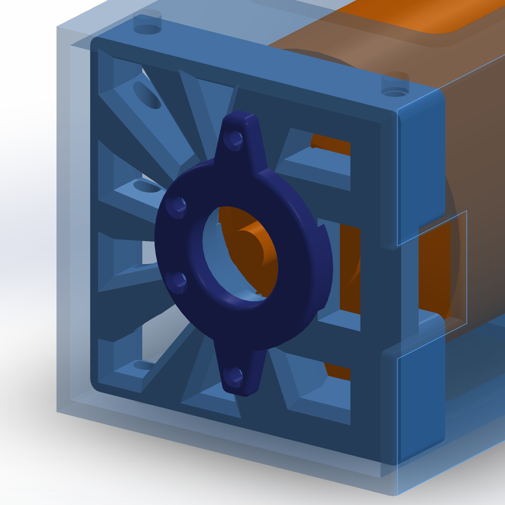
(I have one left and I could just add a second one and add encoders.) The full speed of the machine is about 1000 RPM. The problem I noticed is that in order to just go past the flex of the track and and the friction of the worm gears (blue) about 100W of power are required. That confused the current controller that was more designed for the frictionless propeller.
At full blast the the output of the machine is about 2KW @ 44V batery pack . so that is about 25A per motor so ODrive should be able to handle that.
I look forward any options on from the community
TIA
Maciej
Hello and welcome, I think moving to use the ODrive for your application would be the best choice available.
I’ve been testing with the ODrive for nearly 2 years and have experimented with high and low speeds and various torque levels.
Is the current limit of Odrive 90A per motor or per board? Does it behave nice if the motors stall because of hitting an obstacle? And then recover nicely after throttle is let go.
My regular scenario would be driving up to the wall up to the stop and then reversing, all with the rc controller as input.
If you use closed loop control with encoder feedback then there is no “stalling” per se, in the sense that the motor will apply the commanded torque even at standstill (barring thermal considerations of course). In my application (legged robotics) a lot of work is done while the motor is in standstill, and torque control (as well as velocity and position) is very granular.
With the correct configuration, you should be able to control the ODrive with RC (PWM) input directly.
Ok, thanks for the reassuring I just went full on on ordered the the ODrive with 2 x 63mm (the larger one ) motors and the matching encoders. So the setup will be based on the tested components. With 2KW max power per motor they should be just fine for my machine.
I have seen the 3d printed cases for fitting the encodes for the smaller motors, did someone already did that for the larger motor as well?
ASA I get the parts I update this tread with the progress…
Many thanks
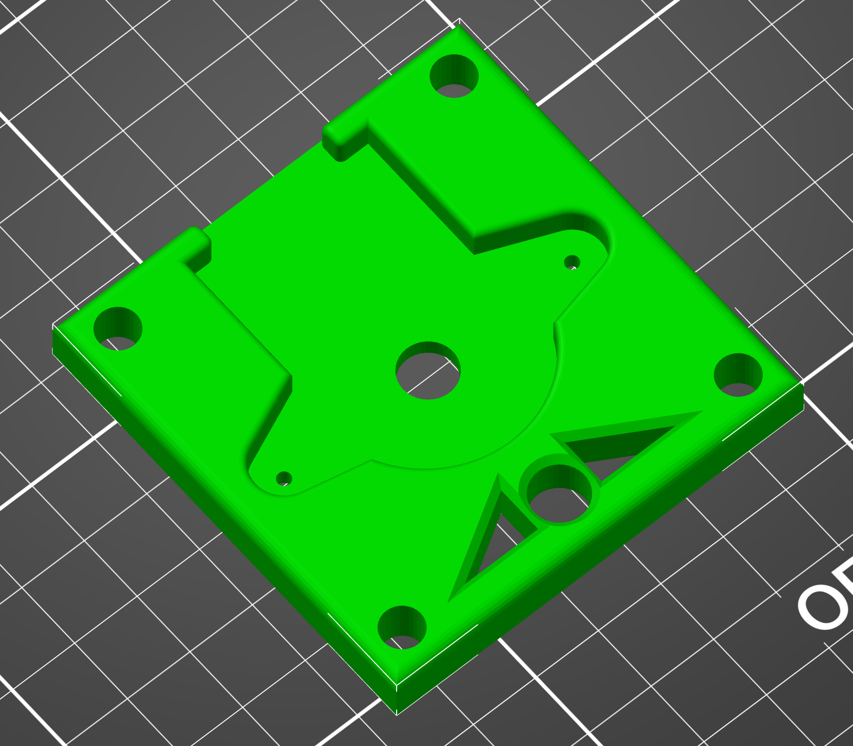
I can certainly reuse the endplate with encoder socket. I just need to combine it with the plate for the worm reduction gear, that I already designed for the previous motor. Have you done it in solidworks?
The files are (step) and are on Grabcad (key word ODrive or Jerry Atrick) and produced by fusion 360, I’m really new to this CAD stuff but suppose you could import and adjust them in Solidworks.
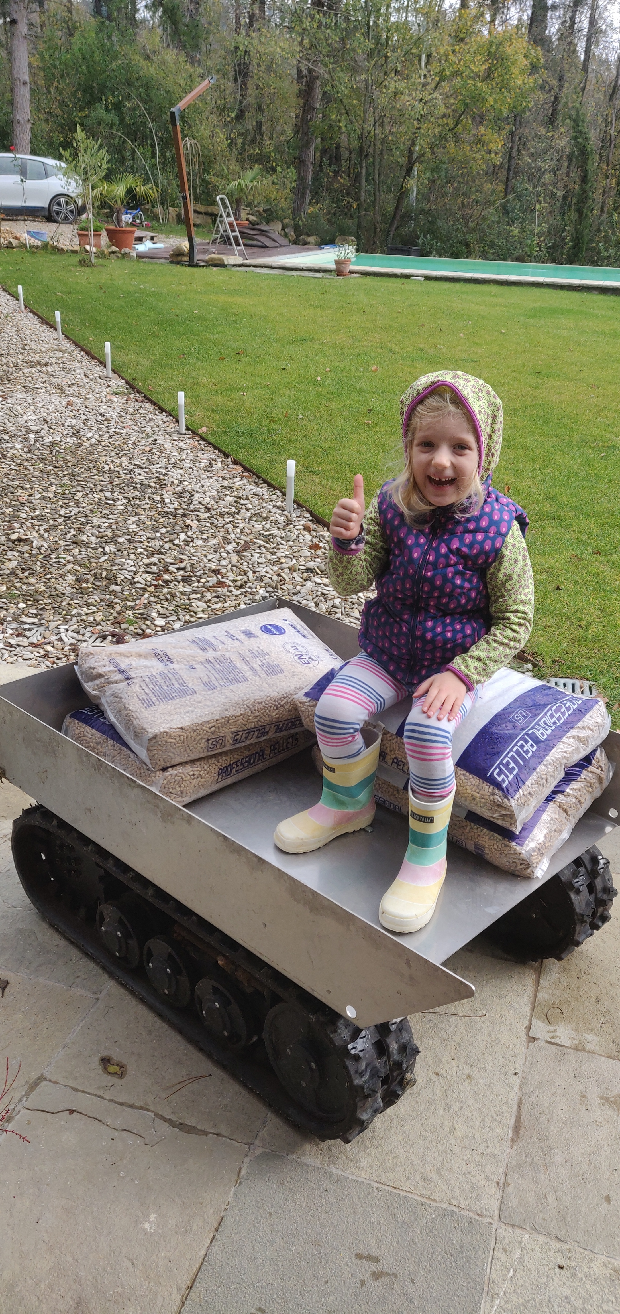
BTW, I love your tank base you built, maybe one day you can attach an air cannon
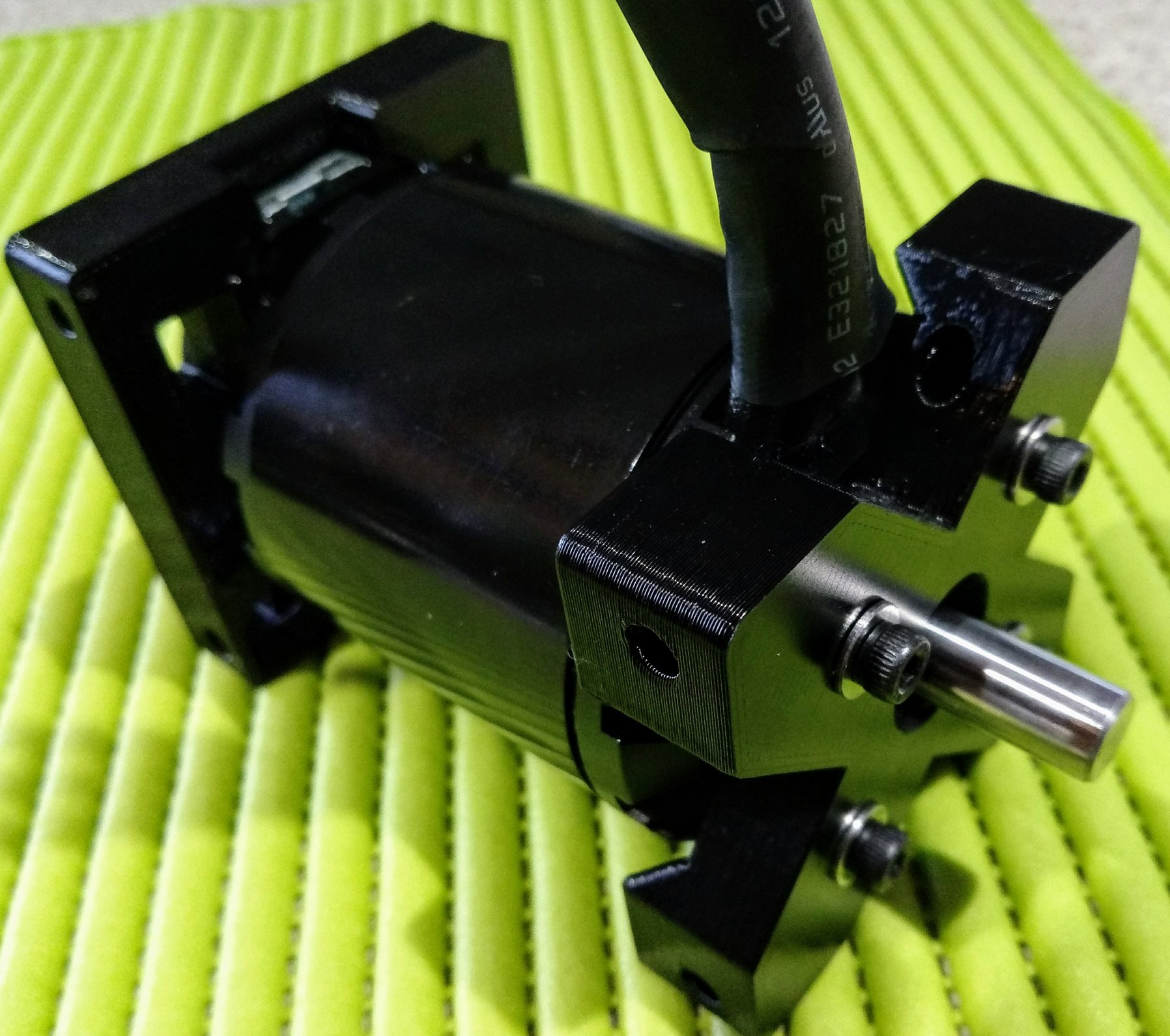
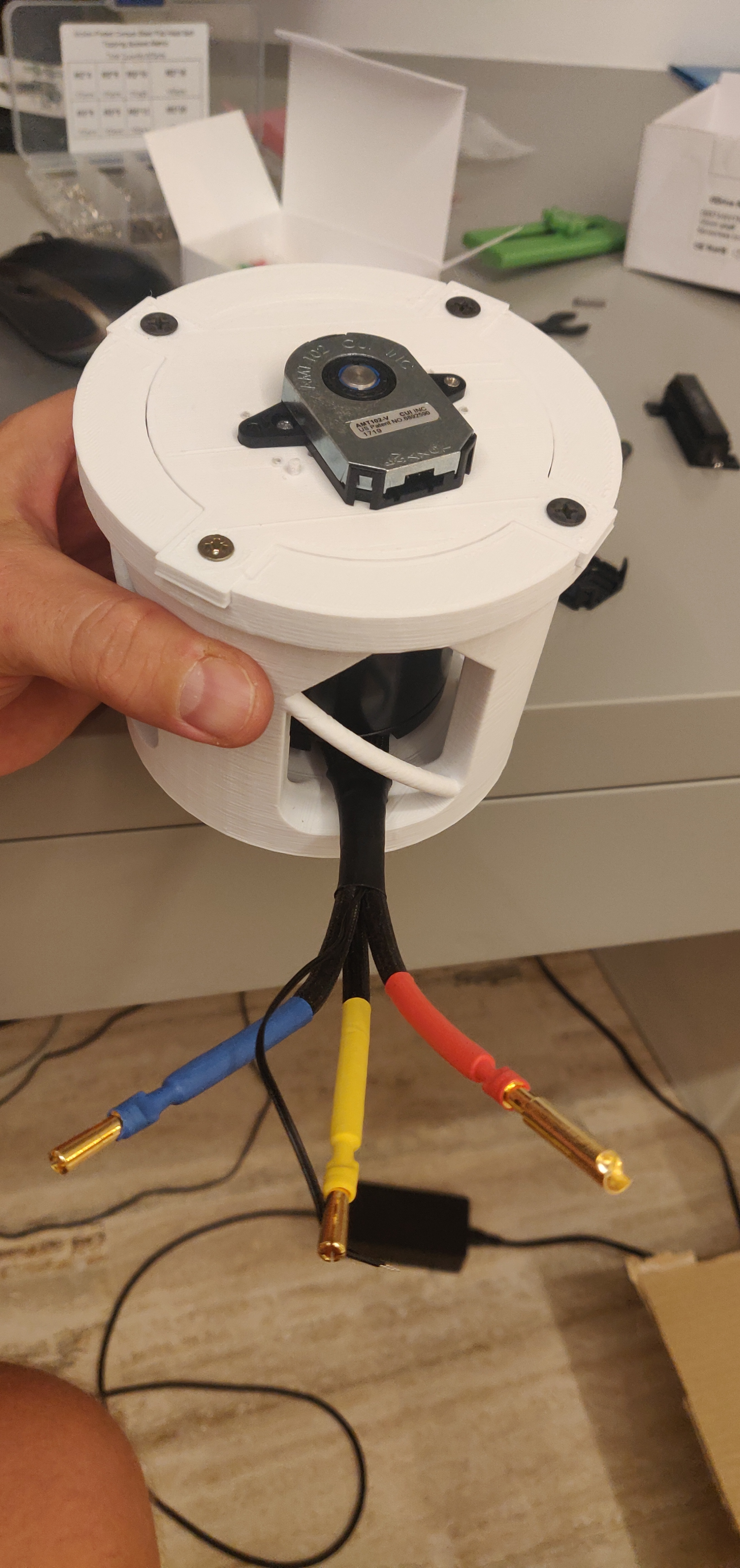
ok so I crafted the first attempt @ motor housing with my gearbox atachment
Compared to my old motor this one has a drive shaft on the other side, but I was able to reuse most of the design.
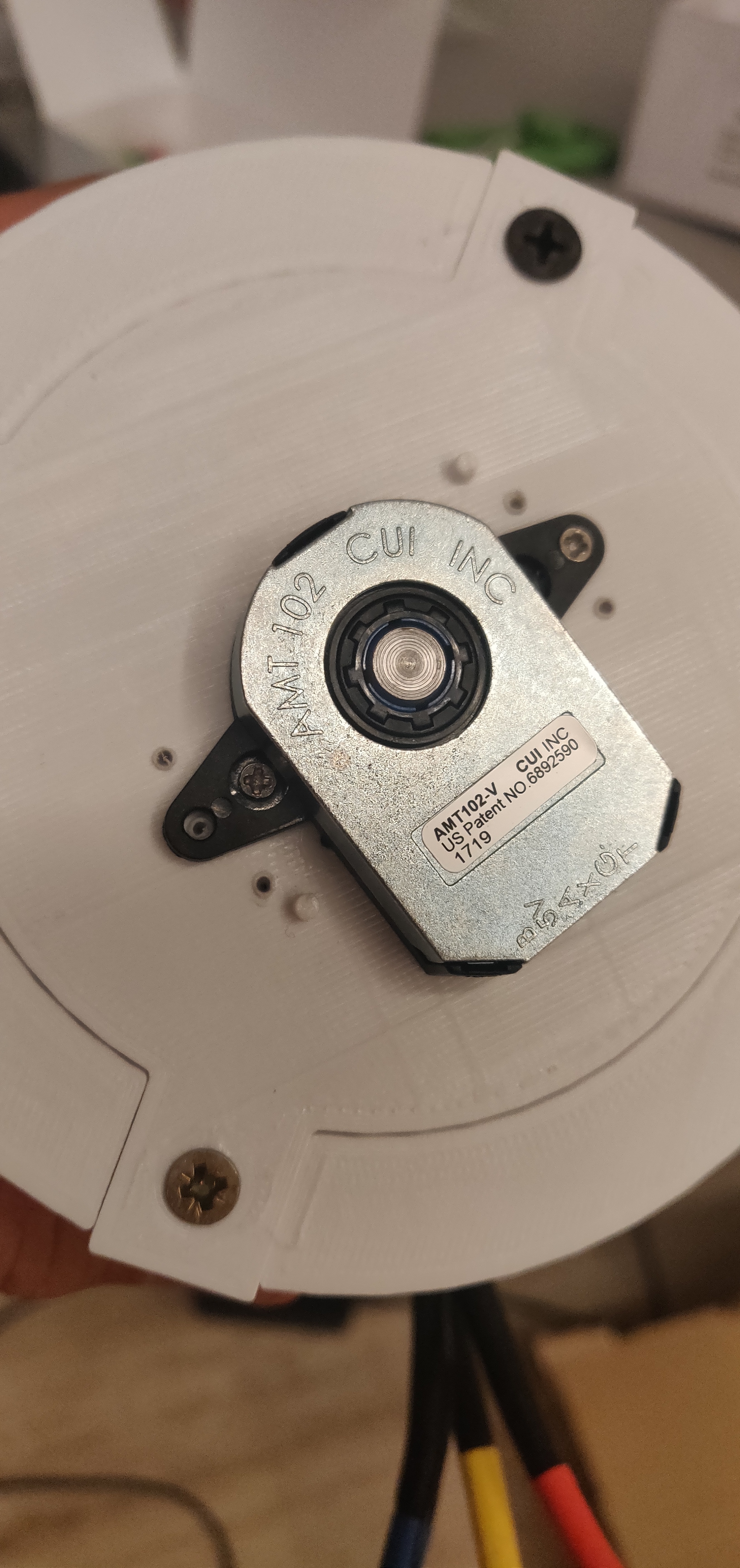
The tricky part is the installation of the encoder.
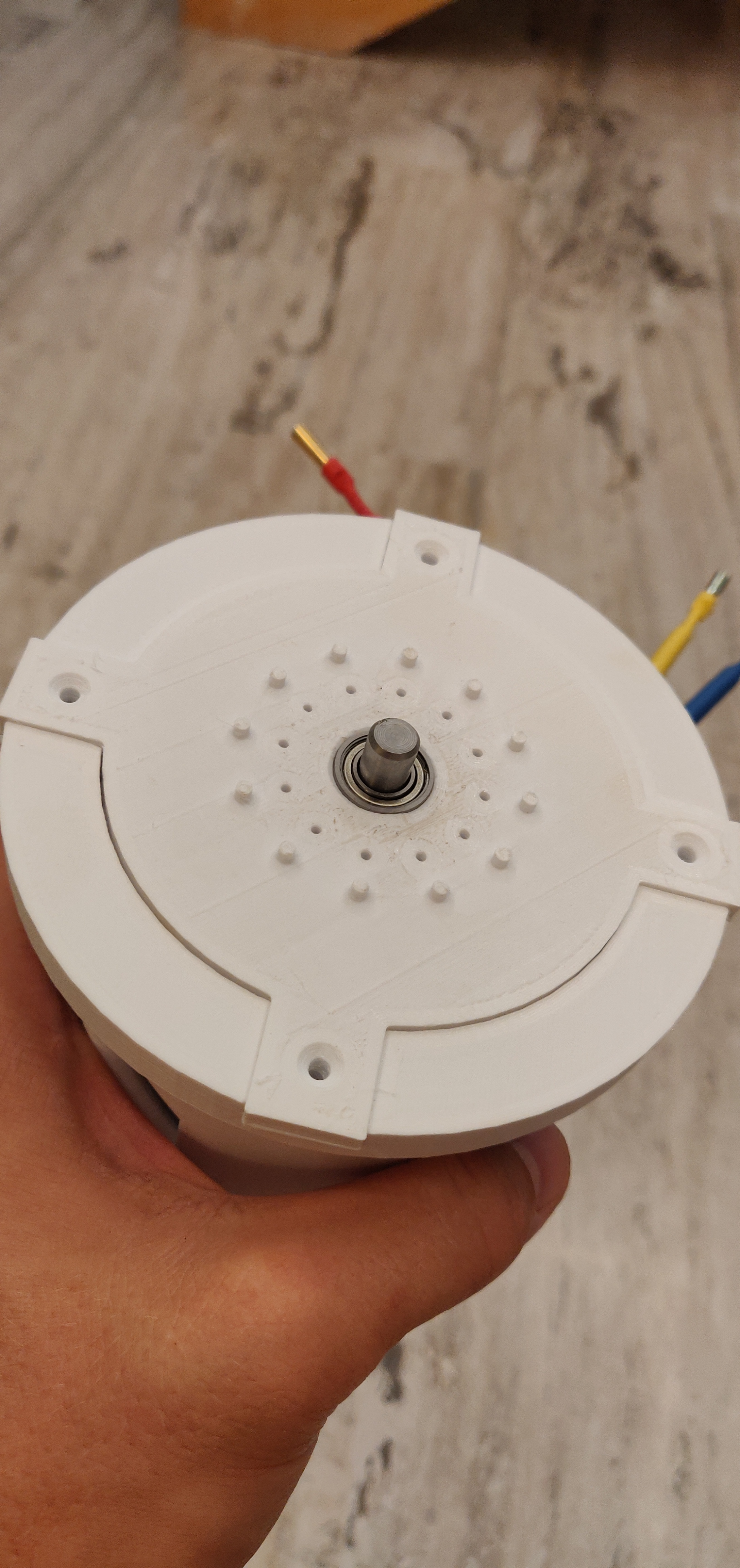
Unfortunately the back shaft came out about 0.5 mm of axis after attaching the back plate for the encoder. It turned out that predone holes would result in tearing inside the encoder. The room for error is here is miniscule.
I managed to reach “no tearing sounds state” but it took 4 attempts of manually re drilling the mounting holes for encoder and 1h+ of playing with the motor screws on the front as PETG is actually giving in a bit on thightening the screws and that affects the shaft center position by couple hundred microns, and that is enought to make the encoder tear a bit
Does any tearing in the encoder is acceptable? or It has to be completely silent? It seems it does not have any bearings inside?
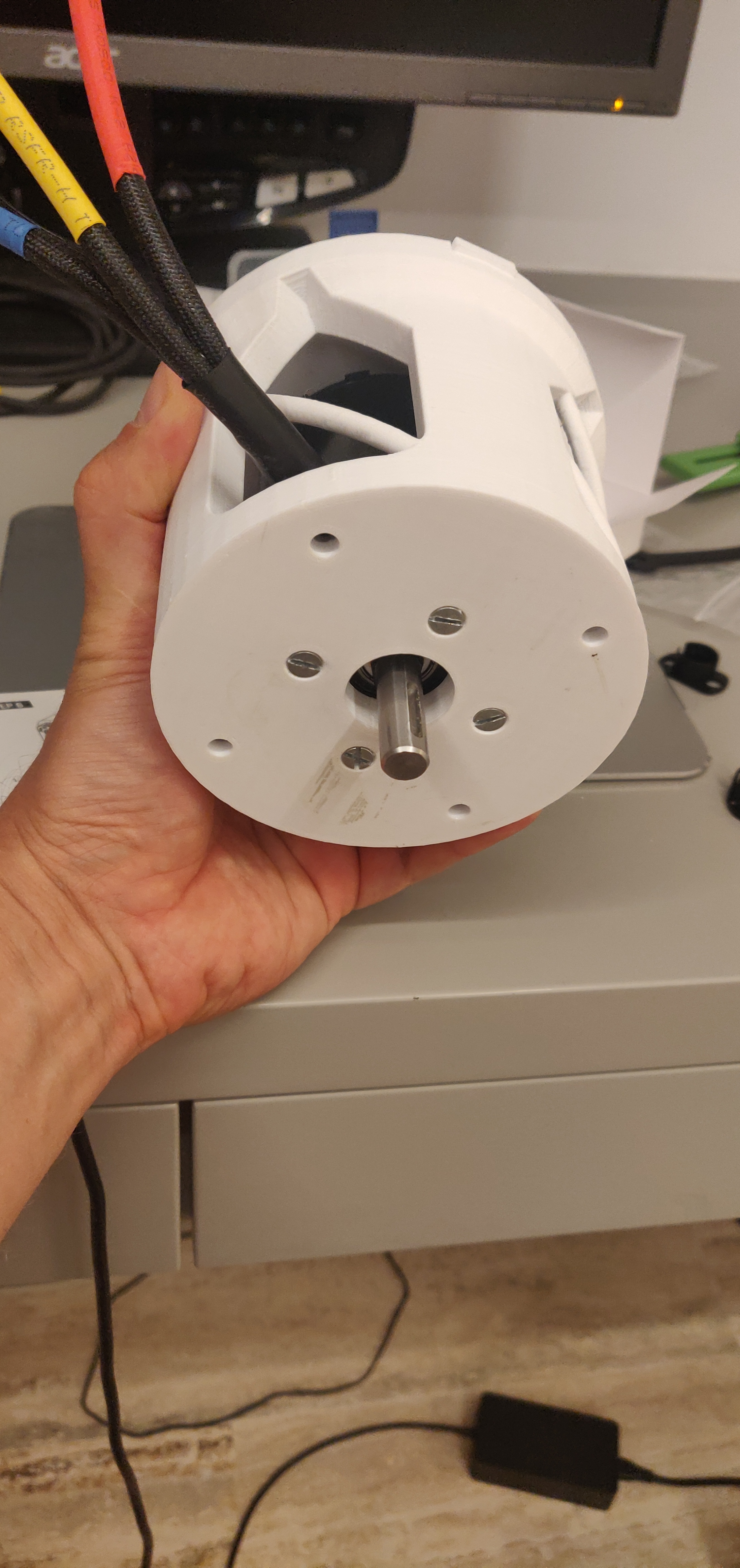
BTW, how the red, blue, yelow colors on the ODrive D6374 150KV motor corespond to the inputs on the controller board? or it doesn’t matter?
Hi, did you try re purposing my encoder bracket? I guess not, it would have saved you many attempts, anyways looks like you’ve got it up ready to run.
“Encoder Tearing”, I was a little worried and that is why I designed a bearing on the tail end of the 6374 shaft (to centralise the encoder) and mine is silent.
Yes, great hint, the bearing should solve this small misalignment. Lucky 8mm is common rollerblade size so I’ll have that tomorrow. I have checked your designs and the one I could reuse (green) is only in STL file that is a PITA to import to solidworks. The STEP assembly is only for your full actuator, that has a different back plate.
Now another problem that I anticipate is that if I’m to redo my endplate for the one with the bearing I need to remove the fragile plastic encoder sleeves. I pushed the black locking sleeve hard , and have no idea how to do it. without damaging it as there is no spare with the encoder. Have you done that Can that be done at all?
Got the bearings and redid my endplate to fit it. Since those were 50c bearings they had some play and the encoder I think still had a bit noise but fixed that with single layer of paper as the washer under one side of front motor mount. I left the first mounting for now as I’m eager to get the machine working.
.
Got RC control up and running and it looks fantastic (very precise) but I see a bit room for improvement for the zero point detection. Now is the part when I will test that mounted on the machine under load. The fact that calibration needs 1 rev on the startup will be weird as it will move 200kg machine by couple cm every time I power it up.
Now a question I have is that possible to use RC input with Ramped velocity control ?
I think it would be much better for my size of the machine with so much of weight and momentum.
I enabled Ramped velocity control and tried to tie it to the pwm input with a modified command
I try to begin by gently pulling the plastic retaining tab on the curved side and lift the encoder at the same time. Apply gradual force to the tab while lifting the encoder metal body and the encoder will come out without damaging the plastic case. It’s good to have a support for your fingers (both the ones pulling the sleeve and lifting the encoder) while doing this so that you don’t accidentally pull beyond the plastic thingy’s elastic limits.
How you proceed next is up to you: Either continue pulling and the ring and back side tabs will come out themselves; or if you want to play it safe, do the first step for the back side tabs if you have clearance (I don’t most of the times!)
I found this to be the most reliable way of removing the encoder. I have changed encoder mounts more than 50 times and I have yet to damage an encoder sleeve with this method.
Removing encoder body from the sleve is relatively easy , the problem is removiing those super fragile shaft sleves from the shaft , the color one and the black one after it was locked in. I think i need to print a rounded pincers just to do that,
I see, I’ve had success pushing those from below with the tip of a wide flat screwdriver, but you need to have clearance to insert the screwdriver under the black sleeve from both sides so as to minimize stress on the parts.
I guess in the long run printing a custom removal tool would be the best.
In addition, regarding tearing, I think that the sleeve position you get on the shaft following CUI’s instructions (plastic wrench & mount tool) is a bit high and tends to grind on the encoder metal casing. I’ve found that manually pushing the moving ring 0.5mm downwards gave the encoder free spin. Of course this does not account for axis offset.
Here is some progres running motors with the tracks in the air.
Calibration proved not to be the problem as 1/40 of the wheel rotation is little.
With mixers on the RC I have nice steering, allowing cornering at full speed.
ODrive is set to 45A per motor and 60k vel_limit so that is around 730 RPM’s. Need to set the RPM sensor on the RC to verify that,
At full blast I have seen 1.26Kw consumption with one track taking 20% more power for some reason. Probably because of bigger track tension on one side or botched bearing,
But ODrive keeps the velocity nicely equal.
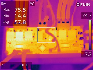
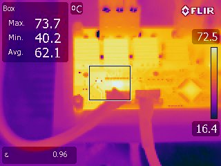
I glued the RC termistor to the heatsink of the less stressed motor with UV glue so it is not very acurate but the temp stays resonable. I can easily touch both heatsinks after a bit of drive.
The only crash I managed to incurre to the Odrive is when I released the throttle at full blast, for a sudden stop. I didn’t have RPI connected at that time but I suspect that momentum kept spining the motor and ODrive decided that vel_setpoint was overshoot to much and crashed. Will log that error next time. but I’d love to b able to use velocity ramping to avoid such a scenario.
So next is hooking up RPI and fixing a RPM sensor and I do some terrain driving.
Ok here is small update.
I let the machine out , and as you can see the control is fantastic.
Having 100kg machine zip around garden with such a speed is fun.
I had an initial problem with machine crashing everytime I let go the throttle rapidly with ERROR_BRAKE_CURRENT_OUT_OF_RANGE. I managed to get it solved by tuning the RC controler and setting ULTRA slow return rate on both channel. Ultra slow in RC terms is like 300-500ms but that was enough for the BRAKE_CURRENT error to go away. I guess it could be avoided in the ODrive as well if you could map the PWM input to the velocity ramp rate
But the command : odrv0.config.gpio3_pwm_mapping.endpoint = odrv0.axis0.controller._remote_attributes['vel_ramp_rate']
does not seem to be valid.
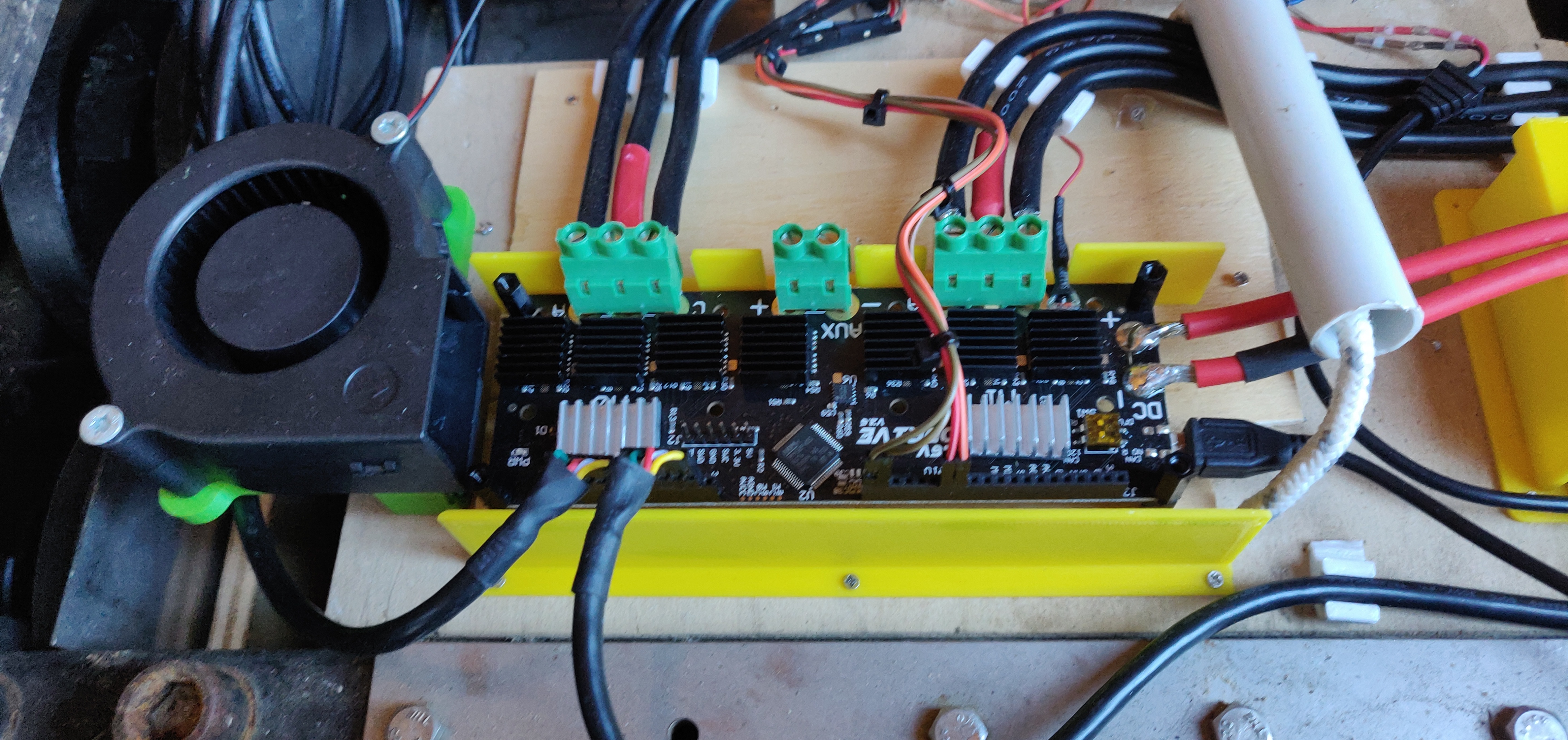
The peek consumption from the pack was @ 2.1kW about 47Amps. The temps stay resonable but I noticed that the driver chip needs a heatsink as well as it goes as far as 74 deg. C.
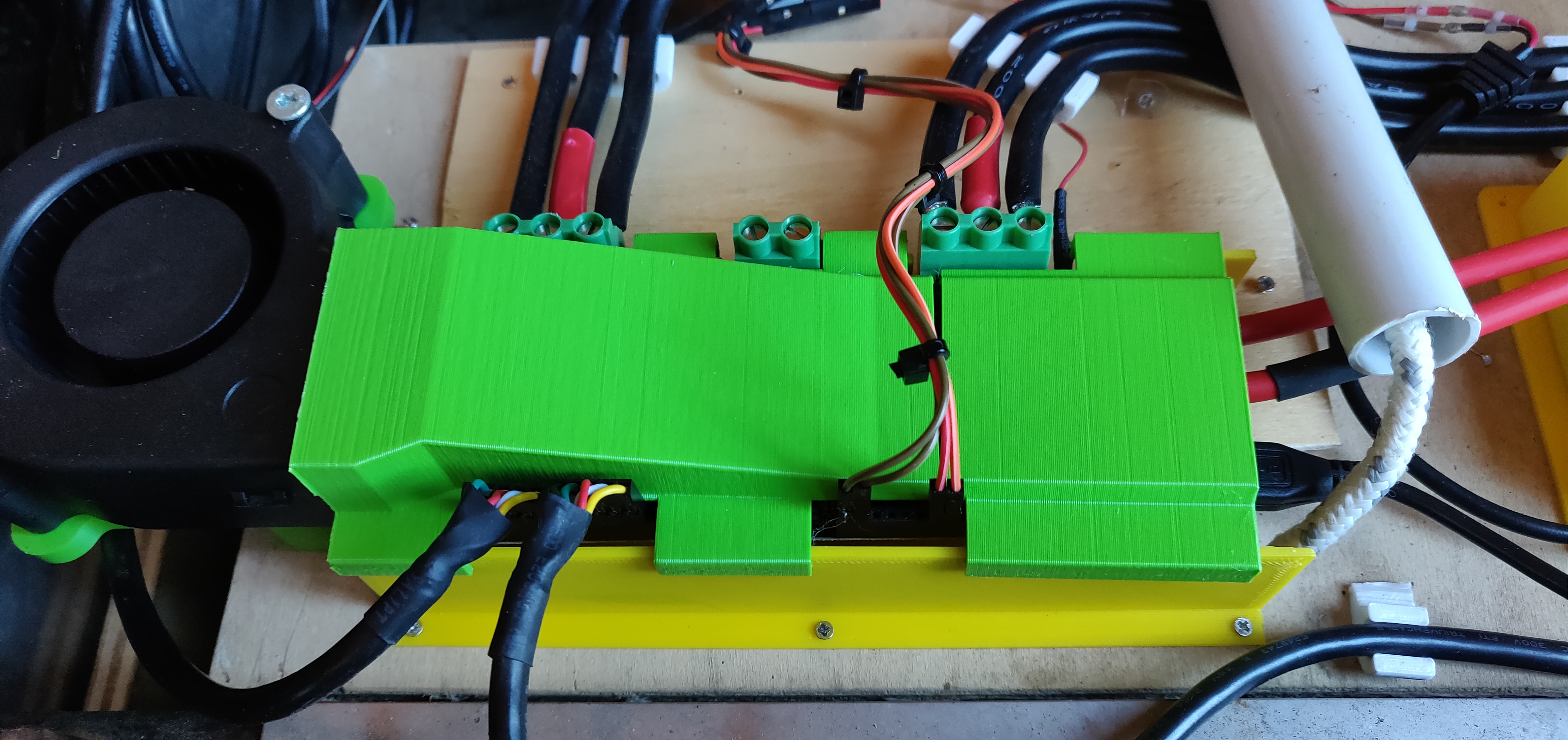
i will print a cover with a blower for the OD next.
Once in a while when I do hit something it will crash OD with ERROR_CURRENT_UNSTABLE. Don’t know if what can be done about that? here is an example. One motor dies when side hit something.
One remaining issue is the calibration on the OD startup. iI the machine is awkward position with a lot stress on the tracks the startup index find will not manage to turn motor to find the index. gets into the clacking sound and stops. for now the solution is subtantial kick into the machine so it does turn the motor once (there is a 1/40 gearing so 2.2cm of the move is the required turn)
I already upped the calibration current to 30A. Is that safe for the
OD 6374 motor? Can I go all the way to 60A?
The motors are another story. They run hot quickly.
Here is the final machine under heavy load with about 200kg of stones.
While it looks like it works. The machine is struggling. After that last stop. It kicked the error. and need to restart OD. That causes a calibration (index find to run) and there is no way that it will turn the motor as tension of the tracks under load is to high. Even with 40A calibration current. I guess the 6374 motors do not have enough torque to move the machine under such a load. While one track did calibrate fine and was working there was no chance to force the second one to pass calibration. I ended up removing the motor from the gearbox and calibrating it again running freely as it would not start up even with the tracks lifted in the air. Only after free spin calibration it started working again as it should until I overloaded it again.
I do admit that I did not run the tuning on the motor. Do you think that can help the case?
Should it be done while free spinning or under load? Under free spin they are silky smooth with acceleration.
Is there a way to read the thermistors of the motors with the OD board, I need a separate code on the RPI to read those?
Now both motors throw.
ERROR_CURRENT_SENSE_SATURATION
But I have no Idea what that that means.
Must be related to setting max current to 60A, at lower currents it crashes with
ERROR_CURRENT_UNSTABLE