Here’s Video
I also have performed another test taking into account what you told about calib_range - decreased the cpr = 1024 and it was able to calibrate with calib_range = 0.09, but still it didn’t change anything in its behavior ( p.s. firstly i tried to calibrate with cpr 4096 and calib_range 0.5, but it failed to calibrate )
odrv0.axis0.motor
Out[7]:
error = 0x0000 (int)
armed_state = 0 (int)
is_calibrated = True (bool)
current_meas_phB = -0.030586719512939453 (float)
current_meas_phC = -0.025983095169067383 (float)
DC_calib_phB = -1.5405229330062866 (float)
DC_calib_phC = -1.5853506326675415 (float)
phase_current_rev_gain = 0.02500000037252903 (float)
thermal_current_lim = 36.71196746826172 (float)
get_inverter_temp()
current_control:
p_gain = 0.10986275225877762 (float)
i_gain = 121.54440307617188 (float)
v_current_control_integral_d = 0.0 (float)
v_current_control_integral_q = 0.0 (float)
Ibus = 0.0 (float)
final_v_alpha = 0.0 (float)
final_v_beta = 0.0 (float)
Iq_setpoint = 0.0 (float)
Iq_measured = 0.0 (float)
Id_measured = 0.0 (float)
I_measured_report_filter_k = 1.0 (float)
max_allowed_current = 60.75 (float)
overcurrent_trip_level = 67.5 (float)
gate_driver:
drv_fault = 0 (int)
timing_log:
TIMING_LOG_GENERAL = 0 (int)
TIMING_LOG_ADC_CB_I = 2586 (int)
TIMING_LOG_ADC_CB_DC = 12846 (int)
TIMING_LOG_MEAS_R = 6602 (int)
TIMING_LOG_MEAS_L = 6606 (int)
TIMING_LOG_ENC_CALIB = 6922 (int)
TIMING_LOG_IDX_SEARCH = 0 (int)
TIMING_LOG_FOC_VOLTAGE = 6870 (int)
TIMING_LOG_FOC_CURRENT = 0 (int)
config:
pre_calibrated = False (bool)
pole_pairs = 10 (int)
calibration_current = 10.0 (float)
resistance_calib_max_voltage = 2.0 (float)
phase_inductance = 0.00010986275447066873 (float)
phase_resistance = 0.12154440581798553 (float)
direction = 1 (int)
motor_type = 0 (int)
current_lim = 10.0 (float)
current_lim_tolerance = 1.25 (float)
inverter_temp_limit_lower = 100.0 (float)
inverter_temp_limit_upper = 120.0 (float)
requested_current_range = 60.0 (float)
current_control_bandwidth = 1000.0 (float)
odrv0.axis0.encoder
Out[8]:
error = 0x0000 (int)
is_ready = True (bool)
index_found = False (bool)
shadow_count = 44 (int)
interpolation = 0.5 (float)
phase = 2.316248893737793 (float)
pos_estimate = 44.234375 (float)
pos_cpr = 44.234375 (float)
hall_state = 6 (int)
vel_estimate = 0.0 (float)
calib_scan_response = 746.0 (float)
config:
mode = 0 (int)
use_index = False (bool)
find_idx_on_lockin_only = False (bool)
pre_calibrated = False (bool)
zero_count_on_find_idx = True (bool)
cpr = 1024 (int)
offset = 415 (int)
offset_float = 1.3510000705718994 (float)
enable_phase_interpolation = True (bool)
bandwidth = 1000.0 (float)
calib_range = 0.09000000357627869 (float)
calib_scan_distance = 50.26548385620117 (float)
calib_scan_omega = 12.566370964050293 (float)
ignore_illegal_hall_state = False (bool)
set_linear_count(count: int)
odrv0.axis0.controller
Out[9]:
error = 0x0000 (int)
pos_setpoint = 0.0 (float)
vel_setpoint = 0.0 (float)
vel_integrator_current = 0.0 (float)
current_setpoint = 0.0 (float)
vel_ramp_target = 0.0 (float)
vel_ramp_enable = False (bool)
config:
control_mode = 3 (int)
pos_gain = 20.0 (float)
vel_gain = 0.0005000000237487257 (float)
vel_integrator_gain = 0.0010000000474974513 (float)
vel_limit = 20000.0 (float)
vel_limit_tolerance = 1.2000000476837158 (float)
vel_ramp_rate = 10000.0 (float)
setpoints_in_cpr = False (bool)
set_pos_setpoint(pos_setpoint: float, vel_feed_forward: float, current_feed_forward: float)
set_vel_setpoint(vel_setpoint: float, current_feed_forward: float)
set_current_setpoint(current_setpoint: float)
move_to_pos(pos_setpoint: float)
move_incremental(displacement: float, from_goal_point: bool)
start_anticogging_calibration()
Well that’s interesting…  I don’t understand how it could move the motor by 10 electrical cycles but the encoder moves only 1/4 rev. Can you see it skipping any poles or does it move smoothly? How far does it turn on calibration? Can you post a video of that?
From your video, I agree it looks like a 4096ppr encoder. Although it’s hard to be certain it’s not 4000?
It’s possible that you have some electrical noise coupling onto your encoder wires, which is causing it to give inconsistent readings when the motor is active (but it’s OK when the motor is off). Although I would have expected this to cause additional counts, not fewer counts.
You could try lowering calibration_current, and/or placing 22nF capacitors to GND on each of your A and B inputs.
No, it’s definitely 4096, as per the spec ppr is 1024. Plus manual movement also shows this, it’s very sensitive, but i see when the mark didn’t reached it’s origin on which it was 0.
Calibration looks smooth, here Calibration video
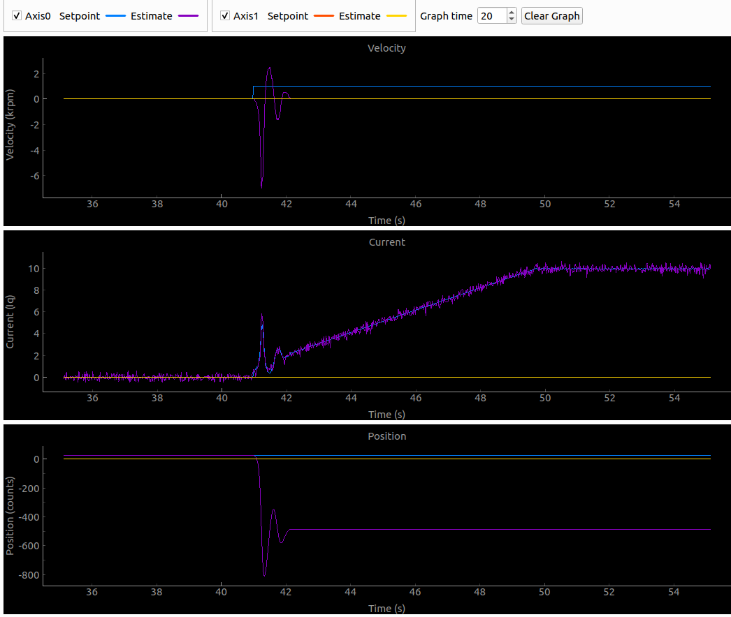
And the output of plots

Everything is same as if it was
cpr 4096 and calib_range 1Yeah, we thought about give a try to the capacitors, but didn’t checked it for some reason. ( Before with other motors it wasn’t improvement, but opposite - the encoders couldn’t calibrate at all always giving different errors )
I’ll check calibration_current and maybe capacitors later.
In that calibration video, it is moving by 1/4 rev… Exactly what I would expect if the pole count was set too low.
Stupid suggestion (another fudge) but have you tried setting pole_pairs to 40?
It could be one of those unusual kinds of motor geometry that multiplies the effective pole count (although it doesn’t look that unusual!)
Yeah, i tried in the past and it was able to calibrate with calib_range 0.1, but behavior didn’t change at all. Double checked right now, same - it moves to pose 800 and back to 0 upon calibration and not spinning in closed loop.
In that case, I’m stumped. Sorry. 
You’ll have to wait for one of the devs to comment.
Looking at encoder.cpp (Encoder::run_offset_calibration), it looks like my understanding of the calibration movement was wrong. It moves by a fixed amount, not dependent on configured pole pairs. But forcing it to do the calibration more slowly or over a longer distance might yield more accurate results - especially if your motor is extremely coggy.
Have you tried increasing encoder.config.calib_scan_distance or reducing calib_scan_omega ?
odrv0.erase_configuration()
odrv0.reboot()

odrv0.axis0.motor.config.pole_pairs = 10
odrv0.axis0.encoder.config.cpr = 4096

odrv0.save_configuration()
odrv0.axis0.requested_state = AXIS_STATE_FULL_CALIBRATION
Can you run this and video it?
If it doesn’t work, try increasing your lock-in current: odrv0.axis0.general_lockin.current
It’s unable to calibrate like this complaining about CPR ( described in previous comments and topic description )
I’m not using firmware 0.5.1, so i have tried changing this odrv0.axis1.config.general_lockin.current ( used axis1 as its easier to film it ).
I changed value from 10 to 15 and 20, then tried also increasing from 10 by 2 - 12, 14…20.
Without any changes.
I’m also unable to add link to the video, because website counts it like a spam for some reason. (As well as all my previous posts )
Hmm… I made a change to your user profile, you might be able to submit links now.
So how far does the motor turn when doing the calibration? On v0.5.1 it should go 1 full turn and then back the other way to 0
This reminds me of a very weird bug I saw when using a Hall sensor.
The “effective” CPR of the Hall sensor would be different if I had set it without first rebooting the drive.
I could get it to calibrate (by doing a binary search on WTF the CPR should be) but then I rebooted and it wouldn’t commutate, and my calibration worked at a different value.
I’d recommend to always reboot after save_configuration.
BTW, these are geared motors, right? Is the Hall sensor on the motor side, and the encoder on the wheel side (ie after the gearbox?)
If so, then you need to divide the CPR by the gear ratio!
yeah, i always do reboot before calibration, I just strictly followed commands that @Wetmelon asked to perform.
Yes, it’s geared motor and here’s the encoder
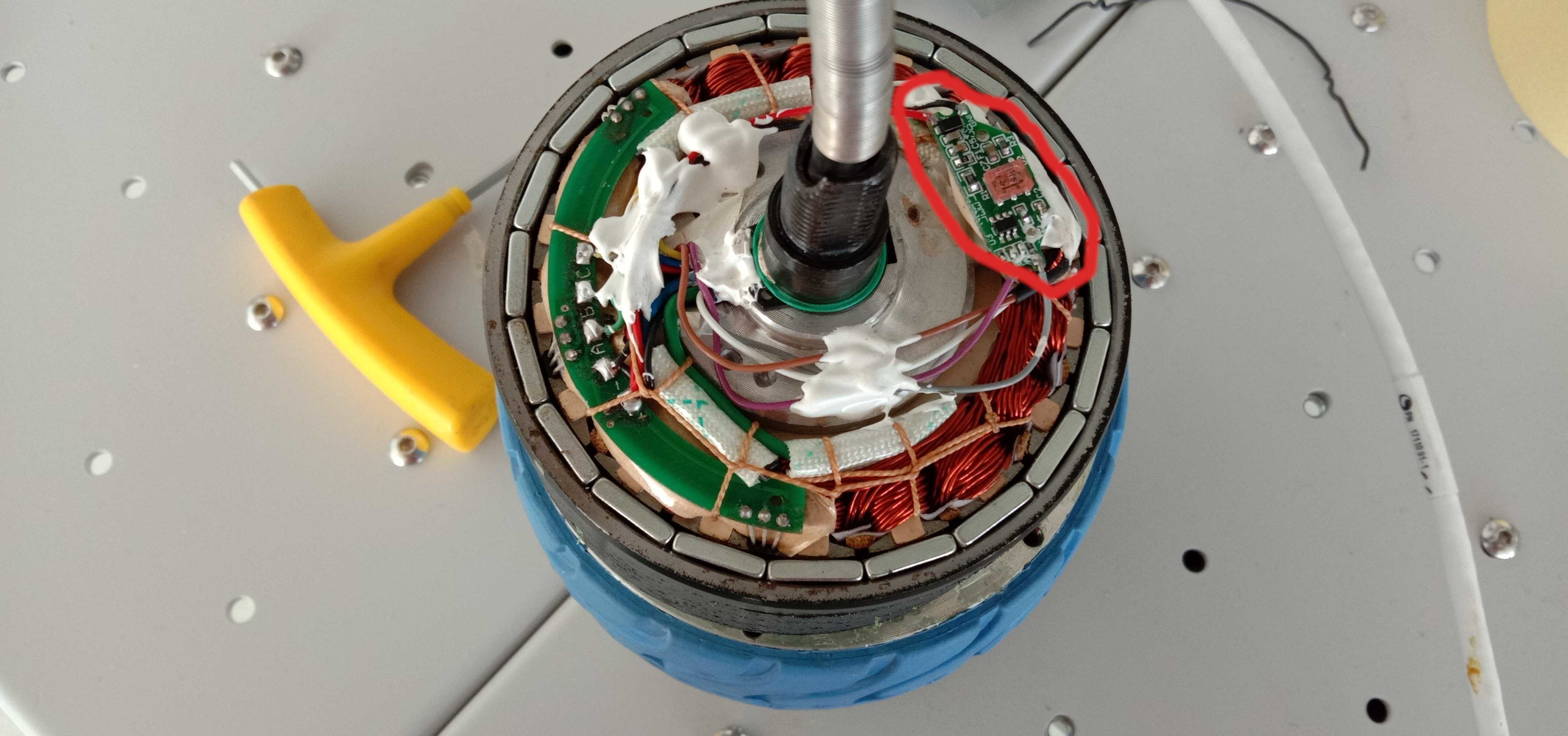
on the cap there’s line on which that pink square slides.
Hmmm. I have the same question as @towen. If you turn the motor by hand 1 revolution, what does shadow_count read? If it reads 4096 then you are going to have trouble controlling this motor because 4096/10 is not a whole number
I can see what looks like an IR proximity sensor, perhaps designed to read an optical track on the inside of the wheel.
So yes, the encoder is on the Wheel side of the gearbox, NOT the motor. That explains all the trouble you’ve been having!
This actuator will be designed to use the Hall sensors for motor commutation and velocity feedback, and the encoder for position feedback ONLY.
This would need the “dual encoders” feature of ODrive that currently ties up both axes. You could try it, but it would only work for one wheel per ODrive.
Your only other option would be to divide your motor CPR by the gear ratio, but you could run into problems, e.g. if you have a 10:1 gear ratio, you’ll need to set a non-integer CPR i.e. 409.6. I don’t know if that will work, and any backlash or elasticity in the gearbox could still screw up your commutation.
2 Likes
I suppose there are just about enough GPIOs that you could hack the firmware to take Hall commutation input from GPIO instead, and then take position and velocity from a single encoder input.
But it would be quite a lot of work I’d expect.
Wow, that’s cool, thanks for your help with investigation, you rock 
Is there any guide about this “dual encoders” feature?
P.S. tried to check that stuff with 409.6 CPR and cpr accepts only integer values, so it would require code changes. Also it couldn’t calibrate with cpr 409 at all, even with calib_range = 1 ( part after dot shouldn’t play big role in this case i believe, but i might mistaken ).
Ok, that’s surprising. If it fails with calib_range=1 then it means it was more than 100% out e.g. if it was expecting to move by 400 counts and it moved by more than 800.
Do you know what the actual gear ratio is supposed to be? (10:1 was just an assumption) It could be 2:1, 3:1 as far as I know (and I’d guess from your video it’s closer to 3:1, because the wheel moved about a third of the way it normally does on calibration)
But as we’ve said, trying to control this motor using an encoder on the wrong side of a gearbox as your sole feedback device isn’t going to end well anyway.
If I were you, I’d try to get Hall sensor operation working using the Hoverboard guide. Because you have a geared motor, you will get much better performance than a hoverboard motor anyway, even without using the wheel encoder.
No, there’s no mentioning of this, but according to this
it looks like ratio is 4:1.
Yeah, we already been performing tests with hall mode, even though it’s not working with correct CPR, which is 256 ( should it also be divided accordingly to gear ratio? ), but works from scratch with all params from Hoverboard guide.
But my boss asked to check “double encoder” feature, so i need to check this…
Haven’t found any guides about it through google, only 2 related topics here…
and
No, to use the Hall sensor you do NOT divide by the gear ratio. It should always be magnet_pole_pairs * 6 i.e. 60. The Hall sensor is on the other side, and reads the motor magnets directly.