GM5208-12 ODrive S1 Configuration

Hello, it is my first time learning about motor and ODrive driver.

I am choosing this gimbal motor because I have a small project that need to have a hollow shaft motor with slipring for sensor purposes. Later I found out that ODrive is not that suitable for low current high resistance gimbal motor.

I feel like it is a steep learning curve for me. Anyone can guide me through the calibration process?

Motor: GM5208-12

Encoder: AS5048A
Driver: ODrive S1

{
“serial_number”: “3974344b3331”,
“fw_version”: “0.6.10”,
“commit_hash”: 3621886066,
“product”: “5.2.0”,
“active_errors”: 0,
“active_errors_str”: “NONE”,
“disarm_reason”: 2048,
“disarm_reason_str”: “DC_BUS_OVER_REGEN_CURRENT”,
“procedure_result”: 3,
“procedure_result_str”: “DISARMED”,
“last_drv_fault”: 0,
“internal_issues”: 0
}

odrv = odrv0
odrv.config.dc_bus_overvoltage_trip_level = 24
odrv.config.dc_bus_undervoltage_trip_level = 10.5
odrv.config.dc_max_positive_current = math.inf
odrv.config.dc_max_negative_current = -math.inf
odrv.config.brake_resistor0.enable = False
odrv.axis0.config.motor.motor_type = MotorType.GIMBAL
odrv.axis0.config.motor.phase_resistance = 7.5
odrv.axis0.config.motor.phase_resistance_valid = True
odrv.axis0.config.motor.pole_pairs = 7
odrv.axis0.config.motor.torque_constant = 0.3308
odrv.axis0.config.motor.current_soft_max = 1
odrv.axis0.config.motor.current_hard_max = 11.3
odrv.axis0.config.motor.calibration_current = 0.5
odrv.axis0.config.motor.resistance_calib_max_voltage = 12
odrv.axis0.config.calibration_lockin.current = 1
odrv.axis0.motor.motor_thermistor.config.enabled = False
odrv.axis0.controller.config.control_mode = ControlMode.VELOCITY_CONTROL
odrv.axis0.controller.config.input_mode = InputMode.VEL_RAMP
odrv.axis0.controller.config.vel_limit = 10
odrv.axis0.controller.config.vel_limit_tolerance = 1.2
odrv.axis0.config.torque_soft_min = -math.inf
odrv.axis0.config.torque_soft_max = math.inf
odrv.axis0.trap_traj.config.accel_limit = 10
odrv.axis0.controller.config.vel_ramp_rate = 10
odrv.can.config.protocol = Protocol.NONE
odrv.axis0.config.enable_watchdog = False
odrv.axis0.config.load_encoder = EncoderId.SPI_ENCODER0
odrv.axis0.config.commutation_encoder = EncoderId.SPI_ENCODER0
odrv.spi_encoder0.config.mode = SpiEncoderMode.AMS
odrv.spi_encoder0.config.ncs_gpio = 12
odrv.config.enable_uart_a = False

Somehow I get the motor moving by using this value, I am not sure if I am doing it right

Step 4: Calibrate (Run Calibration Sequence)
Procedure error NO_RESPONSE. See status bar below for details.

{
“serial_number”: “3974344b3331”,
“fw_version”: “0.6.10”,
“commit_hash”: 3621886066,
“product”: “5.2.0”,
“active_errors”: 0,
“active_errors_str”: “NONE”,
“disarm_reason”: 0,
“disarm_reason_str”: “NONE”,
“procedure_result”: 4,
“procedure_result_str”: “NO_RESPONSE”,
“last_drv_fault”: 0,
“internal_issues”: 0
}

odrv = odrv0
odrv.config.dc_bus_overvoltage_trip_level = 22
odrv.config.dc_bus_undervoltage_trip_level = 10.5
odrv.config.dc_max_positive_current = math.inf
odrv.config.dc_max_negative_current = -math.inf
odrv.config.brake_resistor0.enable = False
odrv.axis0.config.motor.motor_type = MotorType.GIMBAL
odrv.axis0.config.motor.phase_resistance = 7.5
odrv.axis0.config.motor.phase_resistance_valid = True
odrv.axis0.config.motor.pole_pairs = 7
odrv.axis0.config.motor.torque_constant = 0.3308
odrv.axis0.config.motor.current_soft_max = 1
odrv.axis0.config.motor.current_hard_max = 11.3
odrv.axis0.config.motor.calibration_current = 0.5
odrv.axis0.config.motor.resistance_calib_max_voltage = 10
odrv.axis0.config.calibration_lockin.current = 1
odrv.axis0.motor.motor_thermistor.config.enabled = False
odrv.axis0.controller.config.control_mode = ControlMode.VELOCITY_CONTROL
odrv.axis0.controller.config.input_mode = InputMode.VEL_RAMP
odrv.axis0.controller.config.vel_limit = 1
odrv.axis0.controller.config.vel_limit_tolerance = 1.2
odrv.axis0.config.torque_soft_min = -math.inf
odrv.axis0.config.torque_soft_max = math.inf
odrv.axis0.trap_traj.config.accel_limit = 1
odrv.axis0.controller.config.vel_ramp_rate = 1
odrv.can.config.protocol = Protocol.NONE
odrv.axis0.config.enable_watchdog = False
odrv.axis0.config.load_encoder = EncoderId.SPI_ENCODER0
odrv.axis0.config.commutation_encoder = EncoderId.SPI_ENCODER0
odrv.spi_encoder0.config.mode = SpiEncoderMode.AMS
odrv.spi_encoder0.config.ncs_gpio = 12
odrv.config.enable_uart_a = False

I think I got same problem, spi_encoder0 n_errors rapidly increasing, spi_encoder0 status is No Response, when change the gpio12 mode from Auto to Digital the status become BAD CONFIG. when set to SPI_A status become No Response as well

NO_RESPONSE error with AS5048A encoder - Support / ODrive Pro Support - ODrive Community

Your configuration looks great! The issue may just be with your wiring – could you post some pictures?

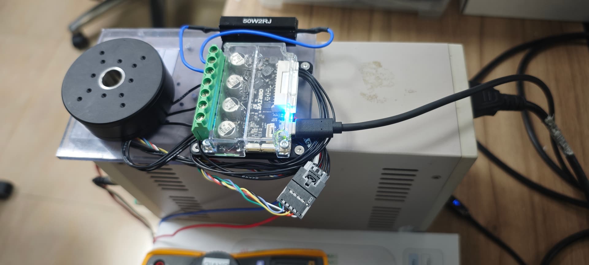
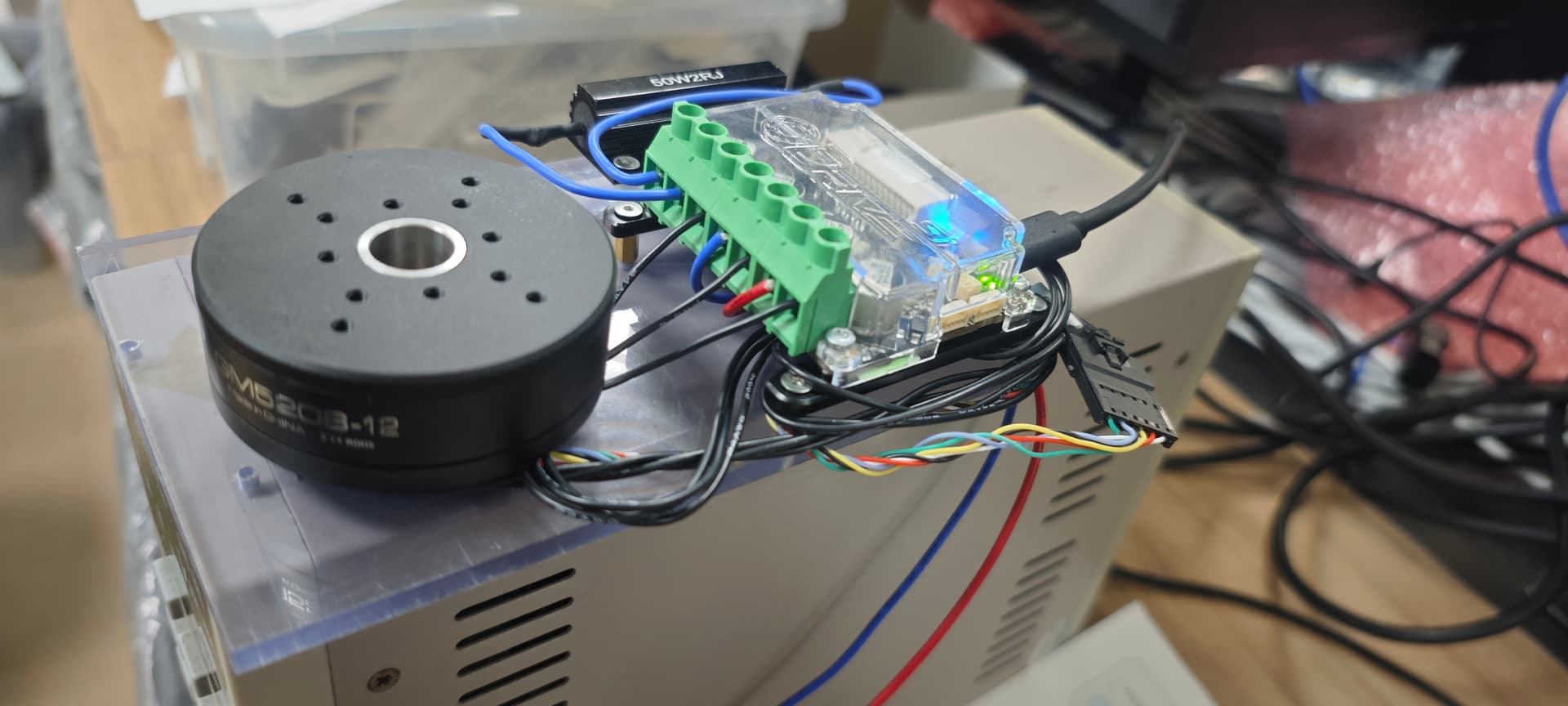
Sorry for the bad images, I already check the wiring once and I will do it again today.
Because the official wiring diagram is so confusing for me, I do check the wiring directly from AS5048A IC directly using multimeter. But maybe I am done something wrong and will check it again today

Green 5V
Blue Gnd
Black MOSI
Yellow MISO
Red SCK
White nCS


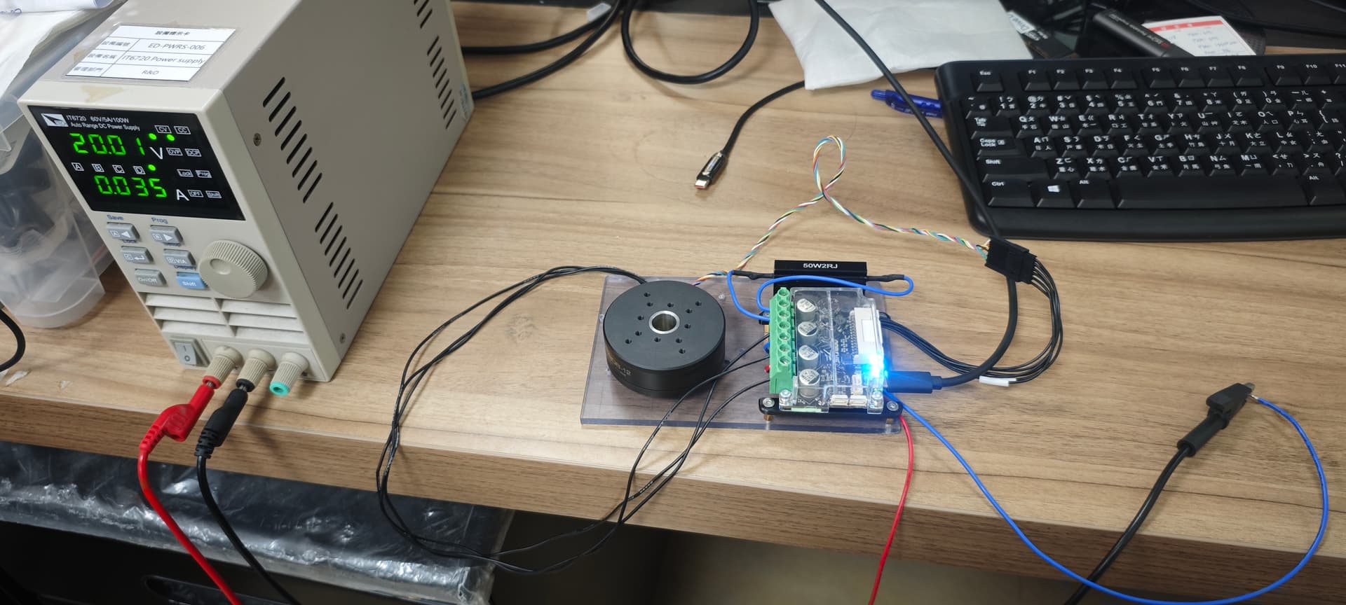
It works now, it might be the encoder signal too noisy, after making sure the encoder cable is not too close with motor phase its working now. its still not great since I got a lot of missing estimate error but at least its working. any improvement that I can make too make the encoder more stable.

Should I reduce the cable length? Is my idea to use quick connecter is a bad idea for encoder? especially its 2 different cable specification

I have the following pinout notes from when I used a similar motor:

25 (5V) - red
26 (GND) - white
27 (MOSI) - yellow
28 (MISO) - green
29 (SCK) - purple
30 (nCS) - black

I can’t comment on the quick connector wiring, would definitely depend on the quality of your crimps – you can always try soldering directly to eliminate that potential point of failure. Unfortunately SPI encoders are intrinsically pretty bad (and the AS5048A in those motors is the bane of my existence), so it may be a bit tricky to get those working really well – you could probably replace the motor’s encoder with an OA1.

You could also try a ferrite ring on the motor phases to reduce EMI. Other than that, any way you can get the encoder wiring away from the motor phases will help. You could hack together a shielded cable out of aluminum foil, wrapping the encoder wire bundle and grounding the foil to the S1’s digital GND (on the 30-pin I/O connector).

If you have an oscilloscope or similar, I can recommend some ways to debug from that.

I am considering using OA1/MA702 as well since it’s been well tested and stable for ODrive but I am not sure whether its also work great for hollow shaft motor with slipring?

Have you ever use OA1 with hollow magnet before? are there any chances that sensor slip ring cable also influence magnetic encoder as well just like with motor phase cable?

Hollow magnets have weaker fields, you can use this to find optimum sensor mounting: https://sensors.monolithicpower.com/ . I’d probably remove the ring magnet and replace it with a normal magnet (Set of 5 Encoder Magnets – ODrive Robotics).

RS485 should be OK running over a slip ring though. Alternatively you can use an off-axis encoder like a RLS Orbis – the S1 will support the 14-bit Orbis (singleturn) over SPI.