Background: Working on closed loop control for a 3d printer. Brand new to odrive. Going to have to use step/dir control; I have two BLDCs from Anaheim Automation, and the 8192ppr encoder sold on the odriverobotics site. Encoders are installed (apparently) correctly.
I’ve gotten to where the motors are working. I calibrated the motor and saved the calibration and set pre_calibrated = True. I can change .controller.pos_setpoint and the motor turns. Then I saved config and rebooted.
Now every startup I have to run AXIS_STATE_ENCODER_OFFSET_CALIBRATION before I can do AXIS_STATE_CLOSED_LOOP_CONTROL. Clearly this isn’t optimal. Reading the (somewhat spare >:) ) documentation suggests that I need “use_index = True” and then “AXIS_STATE_ENCODER_INDEX_SEARCH” before I can set pre_calibrated to “True” on the encoder.
However, when I set use_index = True, and then initiate an index search, I get this:
Axis0:
axis: Error(s):
ERROR_MOTOR_DISARMED
ERROR_MOTOR_FAILED
motor: Error(s):
ERROR_CURRENT_SENSE_SATURATION
encoder: no error
controller: no error
Hi Steve, can’t wait to see ODrive used in a fast 3D printer!
Yes indeed you need to use the index pulse to bypass the calibration. In the near future you may also be able to use an absolute encoder.
As for the current sense saturation, can you please compare the following values? odrv0.axis0.motor.current_control.max_allowed_current
and odrv0.axis0.config.lockin.current
Let me know if that solved your problem, if so I need to go update the docs.
FYI if you wish to change the current sensing range (i.e. change max_allowed_current), you do that by writing to odrv0.axis0.motor.config.requested_current_range, save config and reboot.
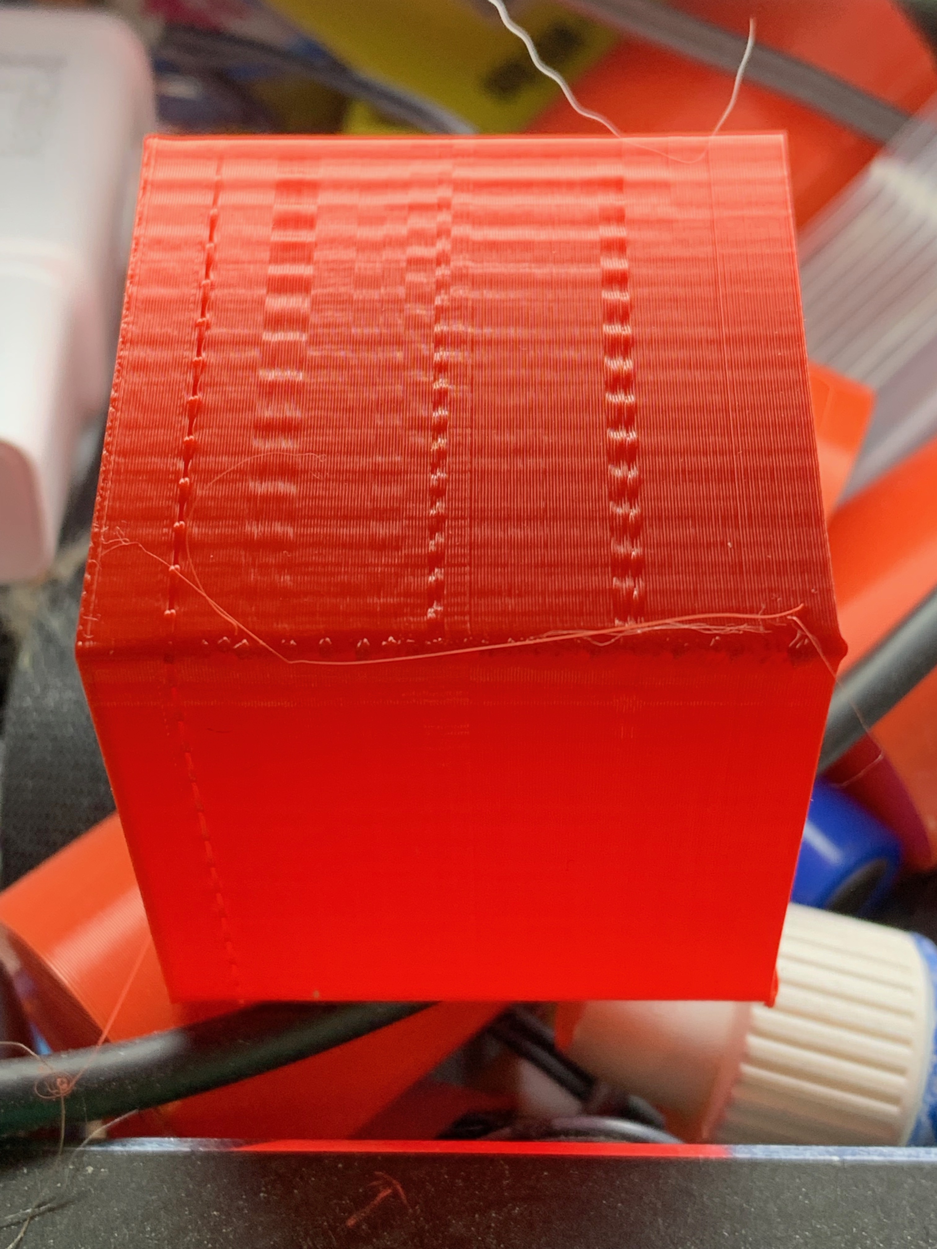
I’m getting oscillation in straight lines. I followed the tuning guide you provided in the getting started docs, but I’m not sure which lever to pull now. Any suggestions? My oscillation is about 1mm wavelength. Any changes I make cause it to get worse
Really interesting! Thanks for sharing. This is a goal of mine at some point, so I appreciate you posting about it.
What kind of motion system are you using? Could the oscillation be coming from something in the mechanical system that is causing the controller to compensate or react to create the wavy lines?
It’s a CoreXY system, a Railcore2 ( RailCore.github.io ). Oskar had mentioned the long belt path could be an issue. I’m using a 3:1 belt reduction. The motors are rated at 3.6A, so I set the max_current to 10A; they’re still room temperature while printing.
Unfortunately, I’ve never tuned these things before. I think I might try reducing the pos_gain; I followed the short tuning guide in the getting started docs, but I might be seeing overshoot. I know at 20 it draws rough approximations of the part .
How much cogging do your motors have? In other words, if turn the motor off and spin it by hand, can you feel well-defined points that the motor “snaps” to? If so, you may want to try the anticogging calibration. You can also help this by increasing the pos_gain and vel_gain.
Also, you will likely want to set <odrv>.<axis>.config.counts_per_step lower
Disconnect the load (belt) from the motor, then use <odrv>.<axis>.controller.start_anticogging_calibration(). Keep your gains high for this calibration. It will do a full turn, then re-enter controlled mode. Once it’s in that mode you can start using the step/direction again.
If that makes a big difference, we need to look at properly saving the anticogging map between reboots, which we’ve been talking about doing for ages.
Ok, that’s what I tried. It made a single “clunk” sound, and did nothing else. dump_errors() showed nothing. My pos_gain is 180, vel_gain is 0.0003 (anything higher and it oscillates). Let me try noodling the pos_gain again and see if it will run the process.
Ok. So odrv0.axis0.current_state never changed from 8. That said, I issued controller.start_anticogging_calibration() and nothing seemed to happen. However, every little bitt it would vibrate, but the shaft wasn’t turning, AFAICT. I tried with pos_gain @ 40, 120, and 200; I can’t increase vel_gain much without oscillation. With pos_gain = 300, heavy oscillation.
These are BLDCs from anaheim automation, FWIW. I’m using the AMT201-V from the odrive shop.
Thats strange. I wonder if it’s fighting with the step/dir for some reason. Can you spit out odrv0.axis0.controller.anticogging? There’s a couple settings in there that could do it
Thanks, I’ll look into that and get back. Might be a little bit; I torched one of the motors with a jam that melted down a phase before I could EPO it. Live and learn, like they say. Later this evening I’ll hook the good motor back up and get the information.
jstevewhite, which motor from Anaheim automation are you using?
EDIT: is that print using a direct drive or bowden? (looks like RailCore is using direct drive by default?)
The picture shows areas where afaict “no (or very little)” oscillations appears - is that correct ? What was wrong with the tuning there ?
I would start to tune without printing and i would use the liveplotter. This way should be much faster and easier to compare.
In addition every change of speed will trigger different frequencies, most important is the change of speed (acceleration setting e.g. trapezoidal), jerk and how long the acceleration phase last (size of speed step). Depending on these factors different PID setting will work or not. So your PID-tune test setting has to include different speed steps in different directions for a given acceleration and jerk setting. Otherwise it might work for a certain print and destroy another… To make it more complex, at a corner your will get different results compared to the middle of the print bed. So in the end you will have to choose a robust tuning, which is of course somehow sluggish (and might show tiny oscillations which can be seen e.g. everywhere on your picture).
I have also a fast fdm printer (with normal steppers, i use 20 g for travel moves and 3-5 g when printing, speed is limited to 500 mm/s because of dropping torque, there i saw big potential) and my plan was to pimp it with odrive. Unfortunately tests (on a test rig) last year showed, that in my opinion at that point in time, Odrive was not able to outperform steppers for this application. Anti cogging was even more experimental, i didn´t try long.
Because Odrive has a lot of power and no missing steps can occur, you could also increase friction (damping), this will reduce the ringing further, but also smear out small features.
As you have shown, fdm is not forgiving for small oscillations…
I am looking forward to see a success here, best wishes !
I’m using the BLY172D-24V-2000 from anaheim automation. And yes, the RailCore2 uses direct extruder by default. You can convert it in a few minutes, but direct is the base config.
Well, the smoothest bits in that picture are the best I can get out of the servos right now. The suggestion is that it’s due to cogging, which seems to make sense because the frequency of the small oscillation is constant at every angle and speed. Unfortunately, those small waves are not even in the same class as what I get from steppers right now.
I plan on testing anticogging as soon as I get another motor - I torched on with a mechanical jam that I didn’t EPO quickly enough. Those motors are a hundred bucks, so it’ll be a couple of weeks before I get a chance to revisit.
The big problem as I see it is that the 3d printer controllers available all use step-dir, so the odrive’s only optimization is from one step to the next. We’ll see how it shakes down.
My concern is less about speed - I can already lay down plastic faster than I can cool it - but wall stacking consistency. Typical 3d printers have layer stacking errors > 0.06mm; RC2, properly tuned, delivers variance < 0.03mm; my goal is < 0.01mm of variance from layer to layer - which is down in the noise floor for the physical system.
Thank you for sharing. I want to upgrade my printer at some point to ODrive and wasn’t sure what I can expect. Hope to see you achieve desired results soon! I’ll be following along your posts so keep us updated.
… that is also what i recognized on my test rig. In my opinion, a part of the problem might also come this topic -> Increase Odrive torque stiffness?. But adding a base current (as described in the link) might make the cogging problem even worse.
It seems that the torque stiffness of a well chosen stepper is already quite big because of the higher number of poles, reasonable high kt values and PID-loops add oscillations you don’t have without them. So adding a PID loop adds micro scale problems you have to overcome afterwards with efforts.
500 mm/s is my travel speed limit, cooling is definitely the barrier when printing.
Independently from dynamic problems, If you aim for < 0.01 mm you have to measure it multiple times better (encoder resolution & pulley teeth number vs. steps frequency) this might get really tricky. As long as the variance is stochastic you won´t notice 0.03 mm anyhow. The static and dynamic extrusion rate error is plenty times bigger.

 .
.