Housing for ODrive V3

Hi,

i’d like to make a housing for my ODrive V3. Did anyone do a CAD Model already? I’d like to use simple aulminium sheets that are lasercut and bent using a wooden bar and a table. I’d like to have a DIN rail clamp on the back to mount it easily in the machine along with a LiIon Battery Buffer and a 24V powersupply, fuses, sensor amps and all the other DIN rail stuff I use to have in my machines

I am using SolidWorks ATM but could also switch to Fusion360 (free for Makers and students).

I can laser those sheets for a reasonable price if there is some interest. Anyone?

If someone could provide a STEP-Model of the ODrive V3.2 would be a good :slight_smile:

The housing shall look a bit like this one maybe:
https://us.nanotec.com/products/1043-smci47-s-closed-loop-motor-controller-for-stepper-motors/

Awesome!

I exported a STEP file of the v3.2 board and checked it into the repository.

If you are used to SolidWorks, then I would highly recommend trying Onshape. It feels very similar, but is a lot cleaner imo. It’s free for public documents.
Incidentally, here is the design that I’m making to lasercut the jig to go with the kit.

Don’t you think you should use slots instead of holes for the motor mount? If you use slots it will accommodate different sizes of motors. Just a thought.

That is a very good idea! I’ll do that!

I’d like to use those terminal block connectors for motor an supply:

  • two 3-pole for motor phases
  • one 2-pole one for DC-in

the therminal blocks could be 7.62mm/41A rating. The higher current ones tend to be expensice (5€ vs 1.60€)
7.62 Terminal Block Screw Connetcor
20A rated connector

I am not sure if we really need a connector that does 40A+ continous. I think it will work just fine with those 20A rated ones

The hole distance of the STEP file you uploaded (thanks!!) is 6.35mm for the phase terminals and 9.52mm fo the DC one. This is not a common hole distance, so I propose to use 7.62mm distance for V3.3 to make using those connectors a possibilitiy

SWD and encoder should be shielded. The encoder could be a D-Sub-9:

  • 5 pins for the incremental encoder or hall-sensors
  • 2 analog inputs for sin/cos encoder and
  • 1 or 2 digital inputs for limit swichtes

the holes are too far out and the disntances do not match teh 7.62mm pattern

one capacitor stands out so the backsheet cannot simply be thermally connected to the MosFETs:

maybe that cap could be placed on the front side? for now, we can bridge the gap with thermal pads

I don’t know what you have in mind for a housing. I made a heatsink that doubles as protection. You can just put standoffs on the other side. Take a look


As you can see there is relief for the cap. I have made 3 of these guys and they are looking pretty good. I have some nylon washers on order for spacers between the HS and the board. When they are installed it will be a very robust way to mount the board. All the holes are threaded for M3.

Here’s a Pic

Nicely done! Yep, that is similar to what’s planed. I also want two sheets, one on the top and one on the back. Not so much machining though, it must be robust, cheap and completely enclosed. No gaps left that could eat matel shavings.

Here is a pic with DIN-rail attached, spacers are still missing.


a different motor controller with similar housing. The MosFETs are thicker compared to the other parts. Maybe just use thicker FETs like the VESC V4 uses, then the cap can stay where it is

Really cool!

So v3.2 sold out a while back, and people have asked me for more stock, I will make another low volume batch at Circuithub again. I didn’t plan on doing any more board design work right now, so I can’t spend the time to do any major changes. That said, there are a few small tweaks I want to make for this batch, so we can sneak in some of the changes you mention.

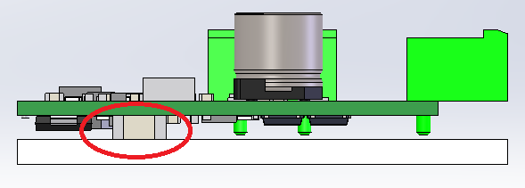
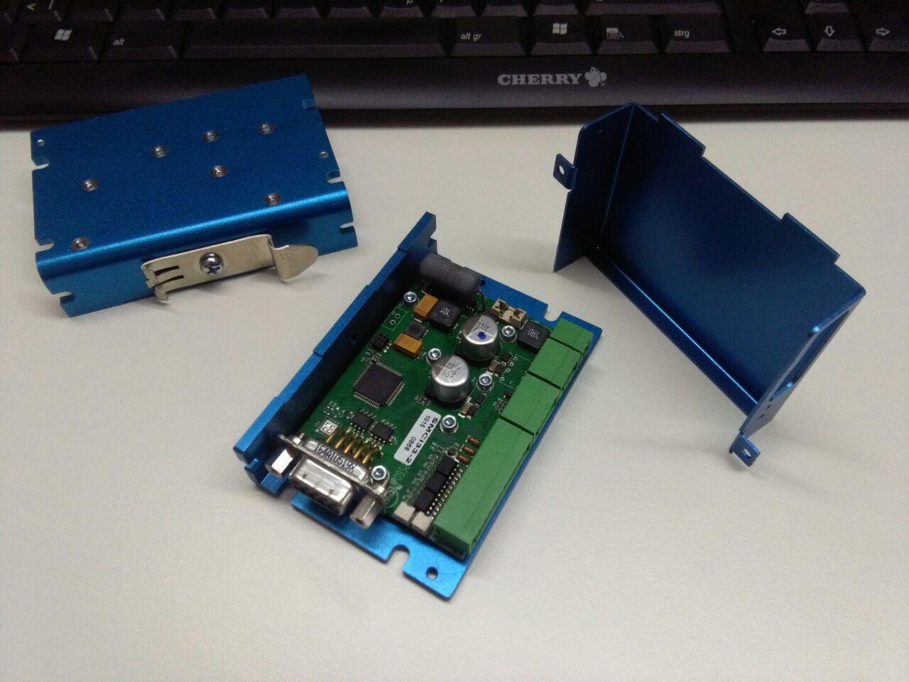
First of all, I can certainly flip that capacitor to the other side, that will be easy.

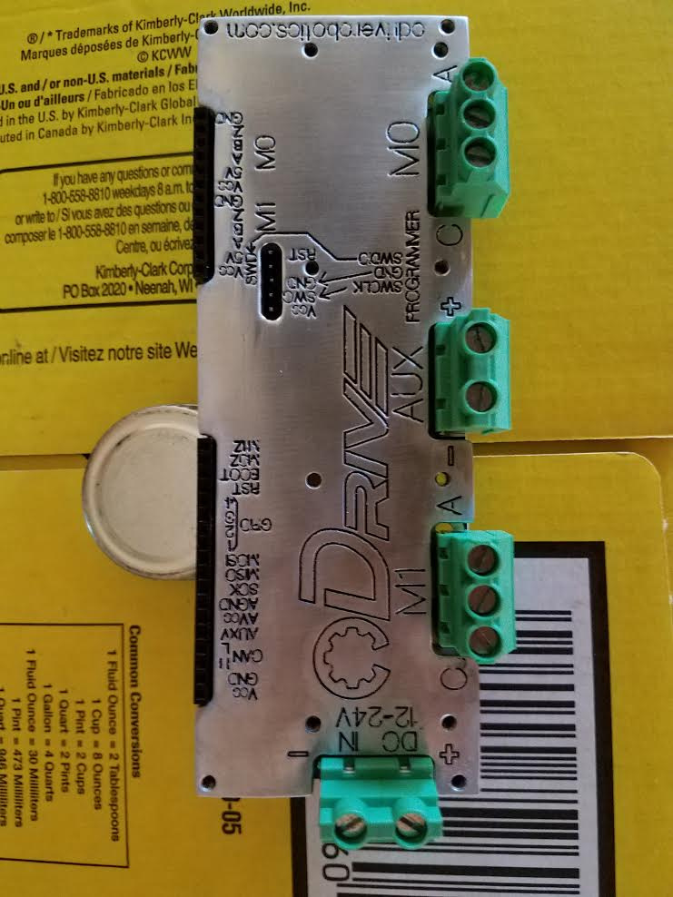
When I picked the screw terminals, I just picked some random ones, I didn’t know what was a standard. I don’t think I will put on the pluggable connectors by default, since they are a bit too expensive, and you need both halves. But I can change to some screw terminals that are very similar to the ones I’m currently using, but use the 7.62mm pitch instead. Then you can desolder them and put your own one on.
I found a 2 terminal and a 3 terminal one. @crossbreak can you please verify that the linked parts are suitable for you, in terms of footprint?

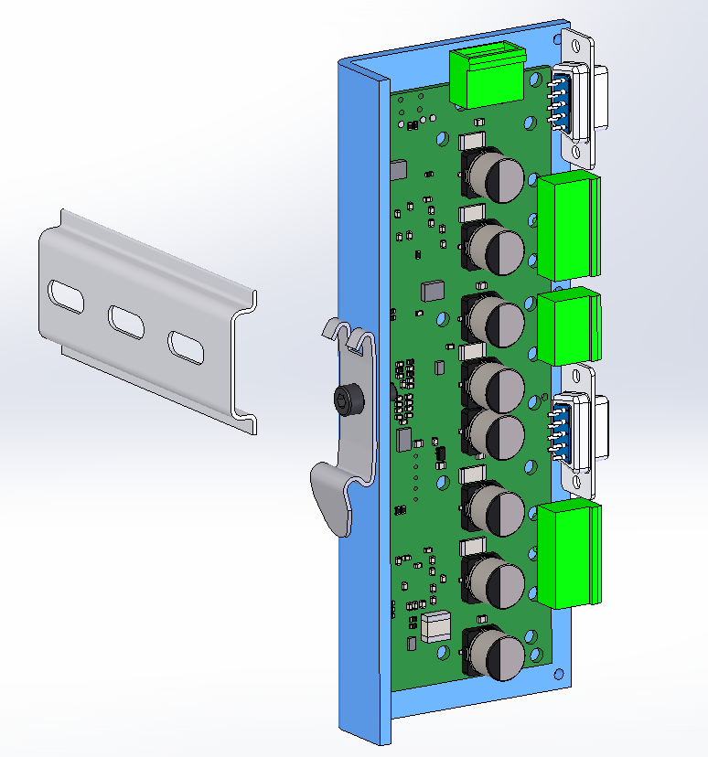
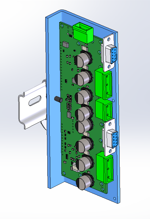
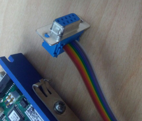
I don’t think I can change the layout of the board enough to accommodate right-angle D-Sub connectors for the encoder lines right now. It’s a good idea though, and I’ll keep it in mind. For your own purposes, you could spend the effort of soldering internal wires from a D-Sub to the encoder ports?

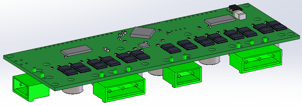
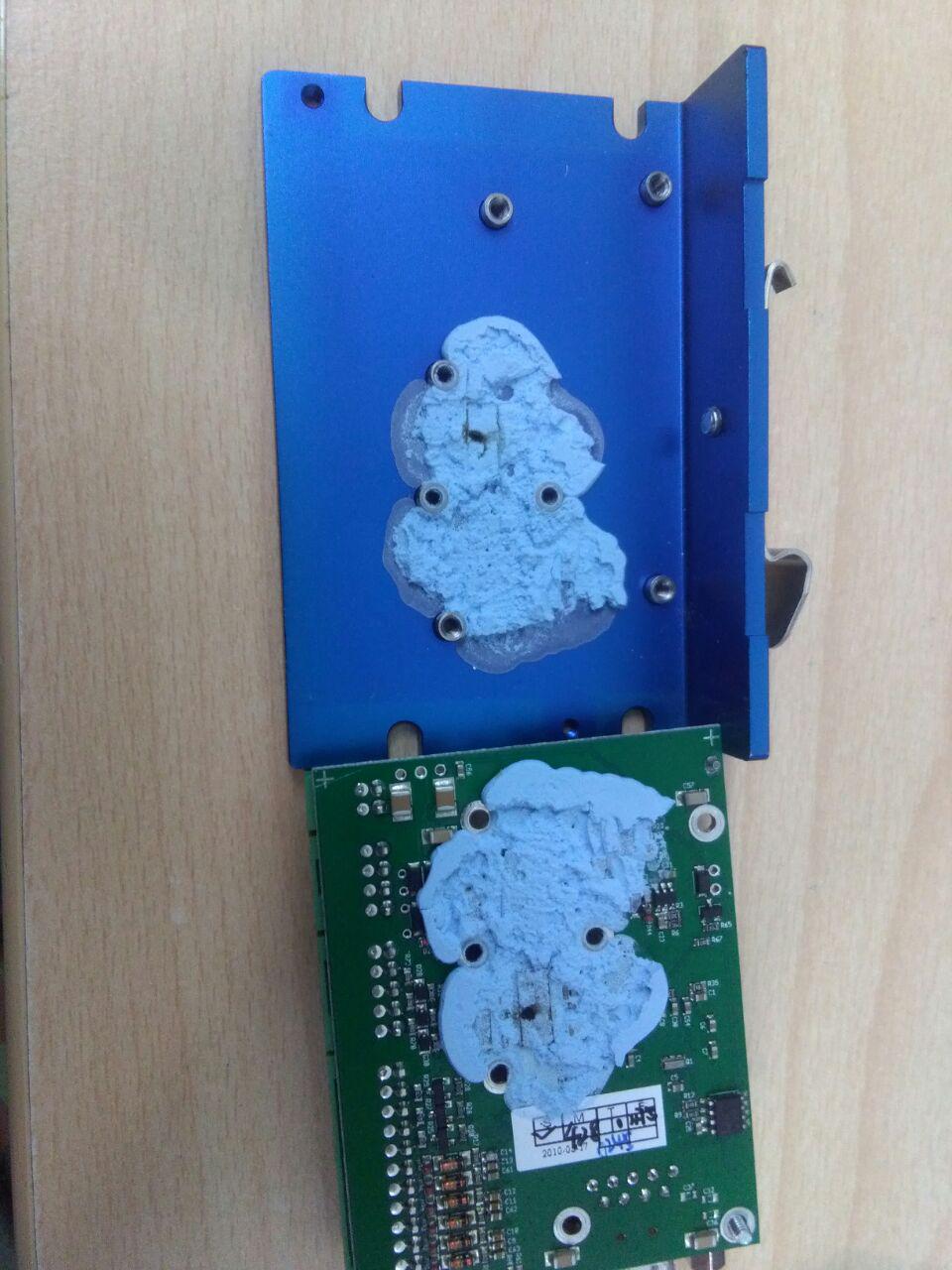
Speaking of soldering, you should be aware that all of the through hole components are actually mounted on the side that you plan to put the heatsinking on. Have a look at the picture on the shop page. Of course you can easily desolder the through hole connectors.

One think to keep in mind is the back-pins of any through hole components. I think you see it already in your CAD drawing. Once the capacitor is gone from that side, your tallest things are the pins coming out the other side from the through-hole connectors. I had this problem on ODrive v2, and I could never fit a heatsink.
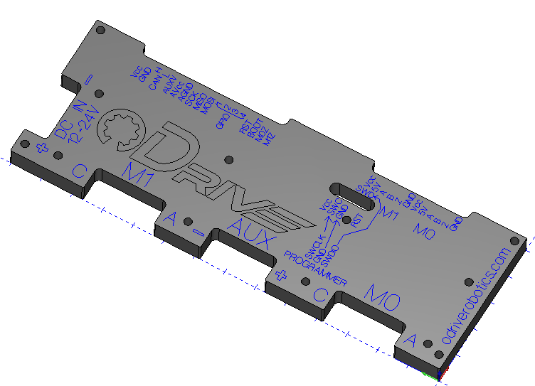
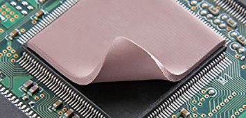
One idea to solve this is to cut a rectangular peice of aluminum from a 3mm sheet using a bandsaw or something very fast and easy to manufacture, and just use that as a heatspreader between the MOSFETs and the case?

In any case (pun intended), I am interested in chipping in for some enclosures.

Sounds good so far. THT-components (through-hole-tech) on the back are a pity, making the unit larger than it would have to be. I think i’ll cut them and solder wires to the board. The DB9 (D-Sub-9) connectors can be of ribbon cable type that are soldered to the clipped pins, later this soldering job could be replaced by the use of IDC-connectors on the board, all we need is double-row pin-headers for the DB9’s

like this one: female DB9 to 10-pole female IDC ribbon cable

The Terminals that stand out on the back can be clipped as well so they cant touch the aluminium sheet on the back and there should be no additional sheet needed for filling the gap between FETs and backsheet.

The 7.62mm terminals are just fine. It would be cool if you could just send boards with no THT components on them so people can decide on which side of the boards they want those components

When designing multi-axis drive with 10 axis or more, then it would be cool if all the interfaces (besides motor+encoder) were on just one side so the board and can be plugged into a motherboard. Edge connectors are capable of up to 40A per contact

The Juicyboard uses PCIe connectors that were made for just 25Watt total, too little for our overpowered board.

I can imagine other types of daughter boards that plug into such an edge connector and have a CAN interace (or different) there, too. for example it supplies current by having 7s Li-Ion batteries and a BMS inside.The box i designed could hold 7 of those 18650 batteries in the same form factor.

OK here is the latest heat-sink. This is the one I like. Simple easy to make and I think it looks Schweeet. The heat-sink alone will be much better than the IC’s alone. But if we need even more cooling I added 4 M3 mounting holes and all we need to do is bolt on any configuration of fins or even a fan. Check It Out!!

1 Like

Those DB9-IDC cables are cool! Actually you could populate the encoder rows with 2 groups of 5 male pin headers, and just plug in one side of the double row IDC connector. Then you have 4 unused pins on the DB9, but at least it works easily I guess?

Hm, I don’t know about clipping the back pins, I tried that with v2, and it was basically impossible to get it short enough, especially considering that a short circuit would be very bad. Also, the voltage regulator (U3) and the main microcontroller (U2) are taller than the mosfets. I can try to flip the regulator over to the other side, but no chance for the microcontroller right now.

One solution could be to just use an appropriate thickness thermal pad:
thermal pad
We can simply cut it to fit over the mosfets to bridge the gap with enough clearance for the tolerance of cut pins, and to clear the microcontroller height?

Hey everyone, I have now added to the shop a version of ODrive v3.3 that has no through hole device mounted, and instead they ship in an accompanying plastic bag. You can select the “THD not mounted” option on the product page:
https://odriverobotics.com/shop/odrive-v33

Do you sell these?
I’d be interested in them.