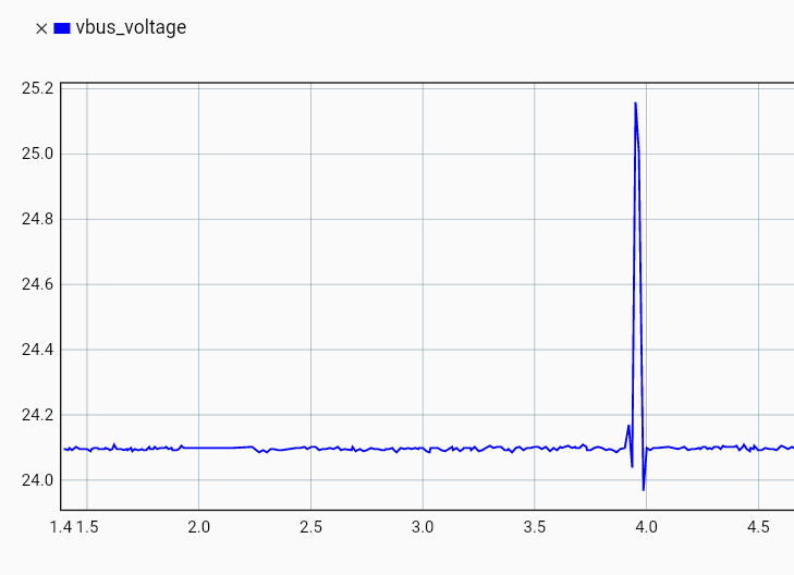
Hi, I am using an ODrive Pro to control a BLDC motor. When doing tests, I get a DC_BUS_OVER_VOLTAGE error; I checked the vbus_voltage with the liveplot and it goes above the nominal voltage of my power supply (24V):
So I am connecting the ODrive Regen Clamp between the power supply and the ODrive Pro, with the 2Ohm breaking resistor (according to calculations I need 0.3Ohm < R < 6.4Ohm). Even with the Regen Clamp connected I get the same error, so I tried setting the value of the breaking resistor through the GUI, but i cannot manage to find it through the Inspector. Should I use the odrivetool instead? Otherwise how do I properly set-up the Regen Clamp with an ODrive? (In the future I plan to connect multiple ODrives to the Regen Clamp, but first I want to test the system with just one)
Hi! What’s your overvoltage trip threshold set to? The regen clamp will clamp the voltage to about 2.5V above the supply voltage, so you need some headroom in your overvoltage trip threshold – with a 24V supply, I’d probably set it to 28V or so.
Thanks a lot for your response! I had the threshold on 25.5V; indeed setting it to 28V got rid of the problem. Though I still have the doubt if I have to define/activate the brake resistor somewhere in the system, as the documentation specify that
“If you set this to a lower value than the true brake resistance then the ODrive will not meed the max_regen_current constraint during braking, that is it will sink more than max_regen_current into the power supply. Some power supplies don’t like this. If you set this to a higher value than the true brake resistance then the ODrive will unnecessarily burn more power than required during braking.”
Anyways I am using the stock resistor that comes with the Regen Clamp (2ohm, 50W), so maybe there’s no need of this (?)
Though I still have the doubt if I have to define/activate the brake resistor somewhere in the system, as the documentation specify that
Not with the regen clamp, that’s fully automatic and always enabled (and doesn’t care what the resistor value is).
Anyways I am using the stock resistor that comes with the Regen Clamp (2ohm, 50W), so maybe there’s no need of this (?)
Correct, this is only applicable for the S1 (and any future ODrives with an onboard brake resistor driver), the regen clamp will block all regenerated current assuming the brake resistor is sized correctly (which yours is – since 0.3ohm < 2ohm < 6.4ohm)
I’m using an ODrive Pro to control a 48 V, 250 W hub motor. Right now I don’t have a regen clamp (or any other way to absorb regenerative energy).
If the motor back-drives and generates current back into the DC bus, can the ODrive Pro safely handle that regen/back current on its own, or do I need an external regen clamp/dump load to protect it from overvoltage?
For reference, I currently have the motor current limit configured to 40 A.
Any guidance on safe setup (and what limits I should watch: bus voltage, regen current, etc.) would be appreciated.
If you’re using this on a power supply (as opposed to a battery), then yes, you would typically need a regen clamp. As a workaround, you can disallow the ODrive from regenerating any current back on the bus, by setting axis0.config.I_bus_soft_min = 0. This will limit the ODrive to operating regions where regeneration (theoretically) doesn’t happen.
Generally, the ODrive will self-protect from overvoltage; the main concern here is the ODrive happily regenerating current and raising the bus voltage above your power supply’s safe limits.
Thanks for the reply! Setting I_bus_soft_min = 0 makes sense for a power-supply setup under normal conditions.
However, my use case is a bit different — I’m using this on a vehicle with a 48V battery connected through an MCB (circuit breaker).
When the MCB is ON (battery connected):
I understand the battery can absorb the regenerative current, so that should be fine.
But here’s my concern — when the MCB is OFF (battery disconnected):
If we pushes the vehicle manually, the hub motor will spin and generate back-EMF. At that point:
The battery is disconnected, so there’s nowhere for the regen current to go.
The ODrive is either powered off or has no battery sink.
My question:
In this scenario (battery disconnected + motor being spun externally), how will the ODrive Pro handle the regenerative current without a regen clamp? Is the ODrive’s self-protection (overvoltage trip) enough, or could the back-EMF through the body diodes damage the FETs/bus capacitors?
Is a regen clamp essentially mandatory for vehicle applications where the motor might be back-driven while the battery is disconnected?
When you externally move the motor, you’ll backpower the ODrive’s DC bus with a voltage about w*KV, where w is the motor’s speed. e.g. if you have a 100 KV motor, and you spin it at 500 RPM (with the Pro powered off), then it’ll backpower the DC bus at 500 RPM / (100 RPM/V) = 5V. Normally this isn’t much of an issue, the main concern comes if other things on the bus will then attempt to draw a significant amount of current. The Pro can handle (while powered off / in idle) backpowering at around 2-5A of current, depending on your cooling, which is a significant amount of power. The main issue is that if you push the vehicle too fast, then the back-emf can exceed the maximum ~60V bus voltage on the Pro, and cause damage to it / other devices on your bus. However, you’d have to be pushing it pretty fast for that to happen (in the aforementioned 100 KV motor case, this would only happen above 6000 RPM). I’d imagine that things on your bus are typically rated for 48V instead of 60V though, so other devices would likely be damaged before the Pro is.
So I’d say as long as:
While the MCB is off, other devices won’t try to draw significant amounts of current from the DC bus (e.g. you have an undervoltage lock-out on anything power intensive / gate it on the MCB state)
The vehicle is never externally pushed at speeds higher than (KV * 48V) RPM
then you’ll be okay
If you really need to prevent back-powering, then you can have a relay or load switch between the Pro and the rest of the 48V bus. That’ll make case (1) no longer a concern (though frankly, I don’t think it’s much of a concern in the first place).
Thanks for the detailed explanation! That clears up a lot.
Based on my motor specs, here’s what I’ve calculated:
Motor KV: 5.83 RPM/V
Rated speed: 225 RPM
Back-EMF at rated speed: 225 / 5.83 = ~38.6V (well under 48V)
Max safe push speed (48V bus devices): 48 × 5.83 = ~280 RPM
Absolute max (60V ODrive Pro limit): 60 × 5.83 = ~350 RPM
Since it’s a hub motor on a vehicle, hand-pushing it is unlikely to exceed 280 RPM, so it sounds like I should be safe without a regen clamp for the MCB-off scenario.
A couple of follow-up questions:
When the ODrive is ON and the battery is connected, is setting dc_max_negative_current to match my battery’s max charge current (along with dc_bus_overvoltage_trip_level = 56) sufficient to safely handle regen during normal braking — without a regen clamp?
You mentioned the Pro can handle 2–5A through the body diodes when powered off. Is there a way to estimate how much current hand-pushing the vehicle would actually generate? Would it depend on the load/speed, or is it mostly negligible at low push speeds?
Thanks for reply
Since it’s a hub motor on a vehicle, hand-pushing it is unlikely to exceed 280 RPM, so it sounds like I should be safe without a regen clamp for the MCB-off scenario.
I agree, as long as you’ll definitely not exceed 280 RPM.
When the ODrive is ON and the battery is connected, is setting dc_max_negative_current to match my battery’s max charge current (along with dc_bus_overvoltage_trip_level = 56) sufficient to safely handle regen during normal braking — without a regen clamp?
The dc_max_negative_current is a trip threshold – the ODrive will disable if it regenerates more power than that. If you want an active limit, you can set i_bus_soft_min. For instance, if dc_max_negative_current is -60 and i_bus_soft_min is -40, then the ODrive will actively limit the regenerated current to 40A, and trip/disable if it exceeds 60A. So it’s good to have both the active limit, and a safety/error limit.
You mentioned the Pro can handle 2–5A through the body diodes when powered off. Is there a way to estimate how much current hand-pushing the vehicle would actually generate? Would it depend on the load/speed, or is it mostly negligible at low push speeds?
It’s all going to depend on the actual motor torque, and how much current everything else on the bus will draw – there will only be as much current through the body diodes as everything is actually drawing.
The most safe thing to do here is to have some sort of relay/disconnect on the ODrive power, or for the other things on the bus. But I’d generally say that it would be hard to exceed a 5A draw – even at 12V, that’s 60W, which is a lot just for quiescents.
We are currently investigating an issue with the CAN communication on our ODrive Pro boards.
The boards power up normally, and USB communication is working correctly. The motors are functional, but we are not receiving heartbeat messages over CAN. We observed that can.error reports BUS_OFF, and can.n_restarts continuously increases.
At this point, we suspect that the CAN module/transceiver may have been damaged, which is why no heartbeat messages are being transmitted.
Our CAN wiring was as follows:
CANH connected to the controller CANH.
CANL connected to the controller CANL.
CAN_GND connected to the DC- terminal (48 V negative).
The Raspberry Pi side uses an isolated CAN receiver, and its CAN_GND is also referenced to the same DC- terminal.
With the board powered and no external CAN devices connected, we measured:
CANH to CAN_GND ≈ 0 V
CANL to CAN_GND ≈ 0 V
and the board still enters the BUS_OFF state with can.n_restarts continuously increasing.
Following few question:
How likely is it that the CAN transceiver/module has been damaged?
Does this behavior indicate a failure of the CAN transceiver itself or the isolated CAN power circuitry?
Are there any recommended measurements or diagnostics to confirm whether the CAN hardware is damaged?
Is there a recovery procedure, or would hardware repair/replacement be required?