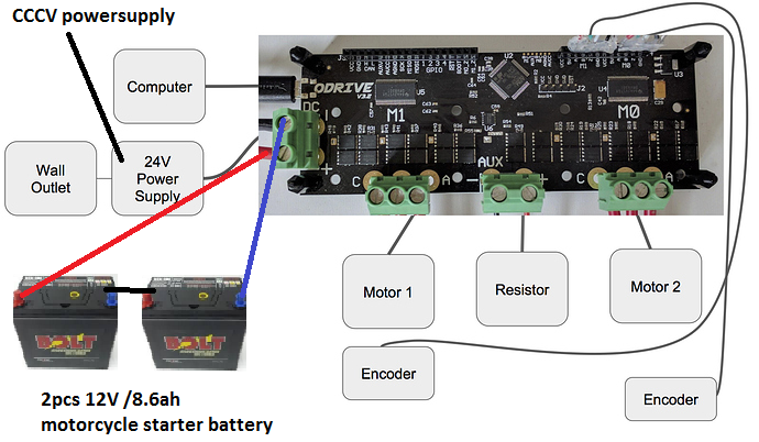
Hi, i’d like to have the most bang for the buck. The idea is to use two sealed Lead-Acid batteries with 12V nominal in series to arrive at 24V total. the idea is that no Batterie Management System ist needed, so the total cost for the buffer is lower compared to a lithium system with equal inner resistance.
What concerns me: Wikipedia states that even though a 10ah Lead Acid battery can be discharged at 100A for a couple of seconds, it can be charged with only 5A, cause voltage would climb to more than 2.65V per cell. That is 1/20 of the discharge current
For comparison: A Sony VCT4 LiIon battery can be discharged with 30A but can be charged with 10A at nominal voltage (3.6V). So the charge to discharge current ratio is at 1:3, much better than the Lead Acid.
Did anyone test gel-type Lead Acid batteries with Regen? How can be explained that Lead acid seems to have completely different inner resistance values for charge and discharge process?
Having a look at cell models, it seems they model only internal resistance (and an RC network) and open circuit voltage: There seems to be no asymmetry in the model with charge and discharge.
So it would seem as long as you don’t over-voltage the cell, and you don’t overheat the cell you should be able to charge arbitrarily quickly.
Some people are backing this up on stack exchage:
Also your alternator matched to your engine size may be capable of fast charging from 60 to 120A without any current limiting and only using Vbat sensing which is ideally 14.2V for desuplhating the battery without excessive electrolyte evaporation.
I once emailed crown batteries company and they say that it’s actually OK to charge at very high current as long as the maximum charging voltage is not voilated with no side effect.
One reason I can think of that you can discharge faster than you can charge is because many of the discharging ratings are with voltage drops down to 7V for a 12V battery. But if you were to charge at the same rate, you will get the same voltage deflection from the Open Circuit Voltage, but 5V deflection on top of let’s say 12V nominal is way higher than allowed (allowed may be 14.2V or so).
Your best bet is to run the battery fairly discharged, like 35% SOC or so, and yeah just make sure you don’t overvolt it, and I think you should be fine.
I think automotive starter batteries are probably the best kind, since their current ratings are very high for their capacity. So maybe a motorbike battery would be good since it’s a bit smaller, but still has that high peak current rating for cranking the engine.
thx for your answers. So Wiki was just wrong. I will try my luck with two 12V - 6Ah gel-lead-acid starter batteries, about 40 bucks together. With a 10A powersupply that is trimmed to 24.4V (about 20bucks, too), the batteries are at ~40% SOC so there is 4V of headroom.
I heard that at rated starter current, 12V batteries drop to around 8V. Meaning a 100A rated battery with typically 6ah would have an inner resistance of 4V/100A= 40 mOhm which is fairly OK for our purpose: With 2V of headroom at 12.2V, max regen current should be 50A, which is half of the rated discharge current.
But what if the voltage rises above 28.4 V?? Will the power resistor kick in?
Edit: Just in case…i now bought two 12V / 8.6ah batteries, 190A rated, for 30 bucks each. I will post my results here as soon as i have them wired up
So one thing to check is the behavior of the power supply during a hard regen kick: does it just sit there and do nothing, or does some kind of OverVoltage Protection kick in, and the power supply turn off?
For using the brake resistor to limit the regen current, that should be fairly straightforward.
Have a look at the code here.
If you put, for example, update_brake_current(-Ibus_sum - 40.0f) in there instead, it would dump any regen current above 40A into the brake resistor. Hence the regen current to the battery is limited to 40A. Of course you can substitute any other value than 40.
You could get the bus voltage involved too, if you want, but that would have to be a control loop that has bus voltage as feedback and that dictates the current.
A voltage dependence would be nice, so there is an error if voltage rises too much, so max velo and deceleration are lowered accordingly. the system should be able to detect a defective or weak battery. One day I want to throw out that resistor. I think I dont really need resistor and the whole 12V converter part. If I was you then i would just drop it and be able to lower the price of the boards
Those adjustable power-supplies all have overvoltage prodection. They just dont output any current if voltage rises above the adjusted value. Below that value they normally supply constant current (15A in my case) till a certain low voltage is reached. Guess around 18V in my case. The batteries should never drop so low. So i dont see any problem here. Anyway, i wont know before i tested. I have this powersupply laying around: MEANWELL SE-350-24 so will just use it. It can be bought for around 40bucks from your local supplier.
The most efficient topology is to put the battery on the bus, as shown.
If your energy storage system (battery or ultra capacitor bank, etc) has a lower voltage than the bus, you can put it on the AUX instead. This means you can do voltage conversion between the bus and the storage. This is both more complicated and less efficient, but is possible.
I think price drops have made this viable 4 of these would be good for 54v 3f 7776 joules
864of it can bring the vbus down I’m new and was wondering can we see the aux voltage off rail so I can calculate determine if it should bleed back to the battery so regen has headroom or keep it on standby for a fun jolt? think plaid ludicrous mode. 13.5V12F 13.5V 12F Super Farad Capacitor Module Kit DIY Power Supply | eBay