Hi - let’s please keep this in one thread so that things can stay organized.
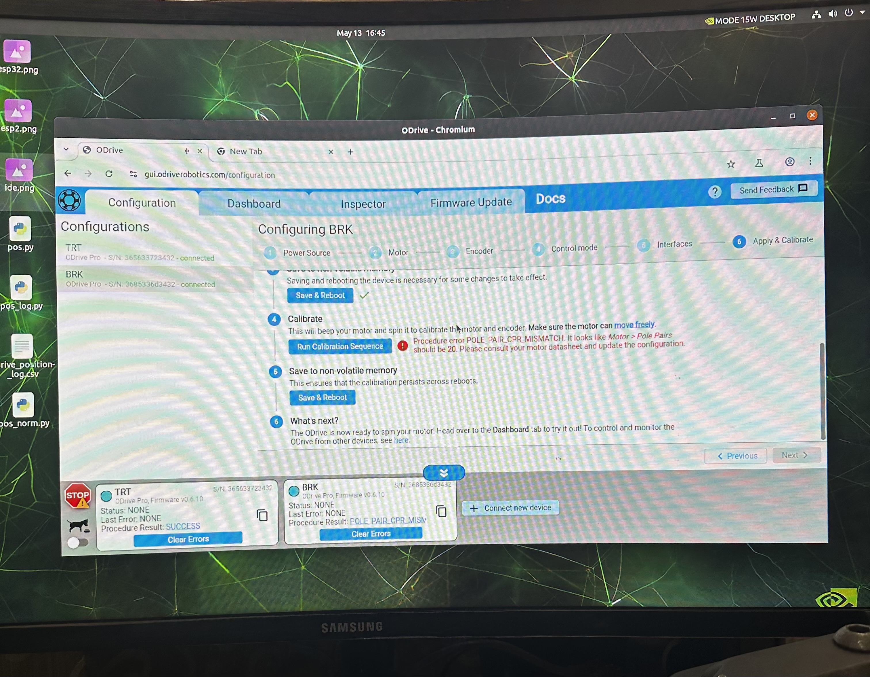
Can you show how your SPI encoder is mounted over the motor’s shaft magnet? I’m guessing you have some error or misalignment there that’s causing this issue.
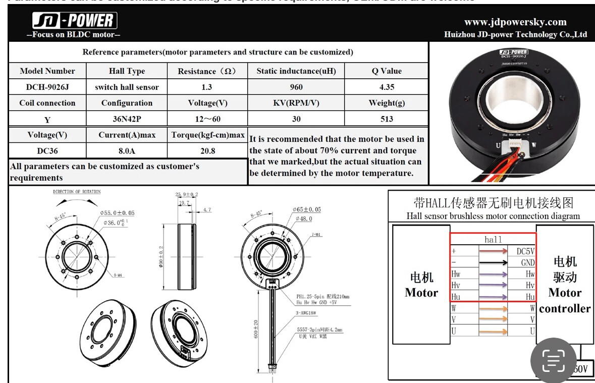
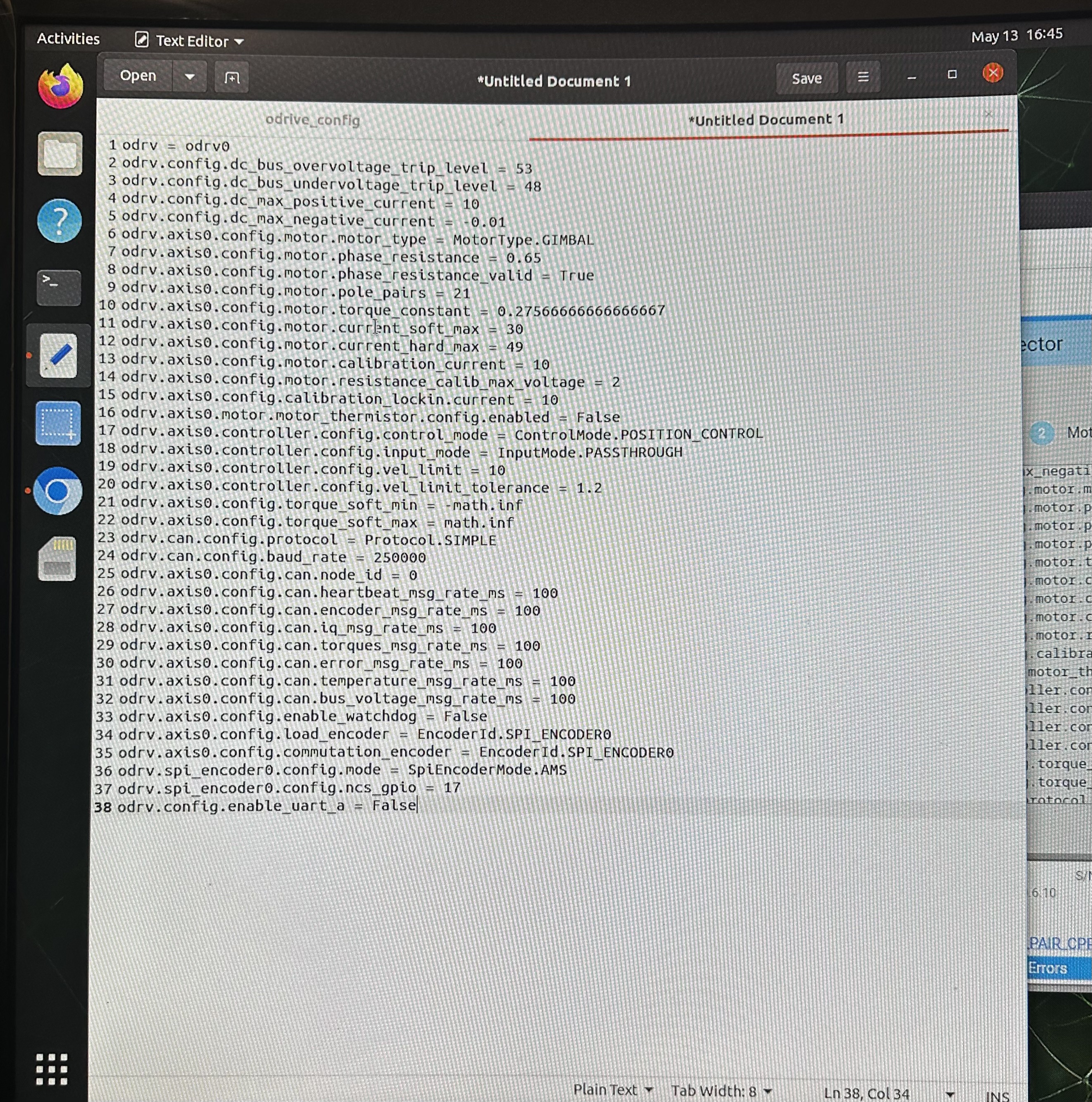
Also note that your motor is rated for 8A max, but you set the motor’s current limit to 30A. I’d recommend reducing that to 8A, as well as the calibration current and calibration lock-in current.
Also could you please provide a clarification concerning built-in Hall Encoder of motor, does it actually require reconfiguration each time after a power rest?
No, halls don’t need recalibration on startup (only incremental encoders do), however note they’re pretty low resolution, so you’ll want to use a higher resolution if possible, for good position control.