Motor Model Temperature Compensation and Field Weakening

Hi all,

I am using a motor that has relatively good characterization data available from the manufacturer, and I have support from them to get more information if needed. There’s two things I’m interested in. First being Temperature Compensation of the motor model parameters. Second being enabling Field Weakening (and any other “advanced” features to aid in performance/response, like dI_dt_FF_enable).

For a bit of background, I am using the ODrive Pro over CAN in Passthrough Torque Mode (I want as direct control of torque as possible). Since I’m using it in Torque mode, I need an accurate model of the torque (as accurate as I can get I guess). The application will see quite the temperature swing, which does have a noticeable impact on the motor parameters like Kv and Kt.

For example, these curves were provided for 25C and 155C:

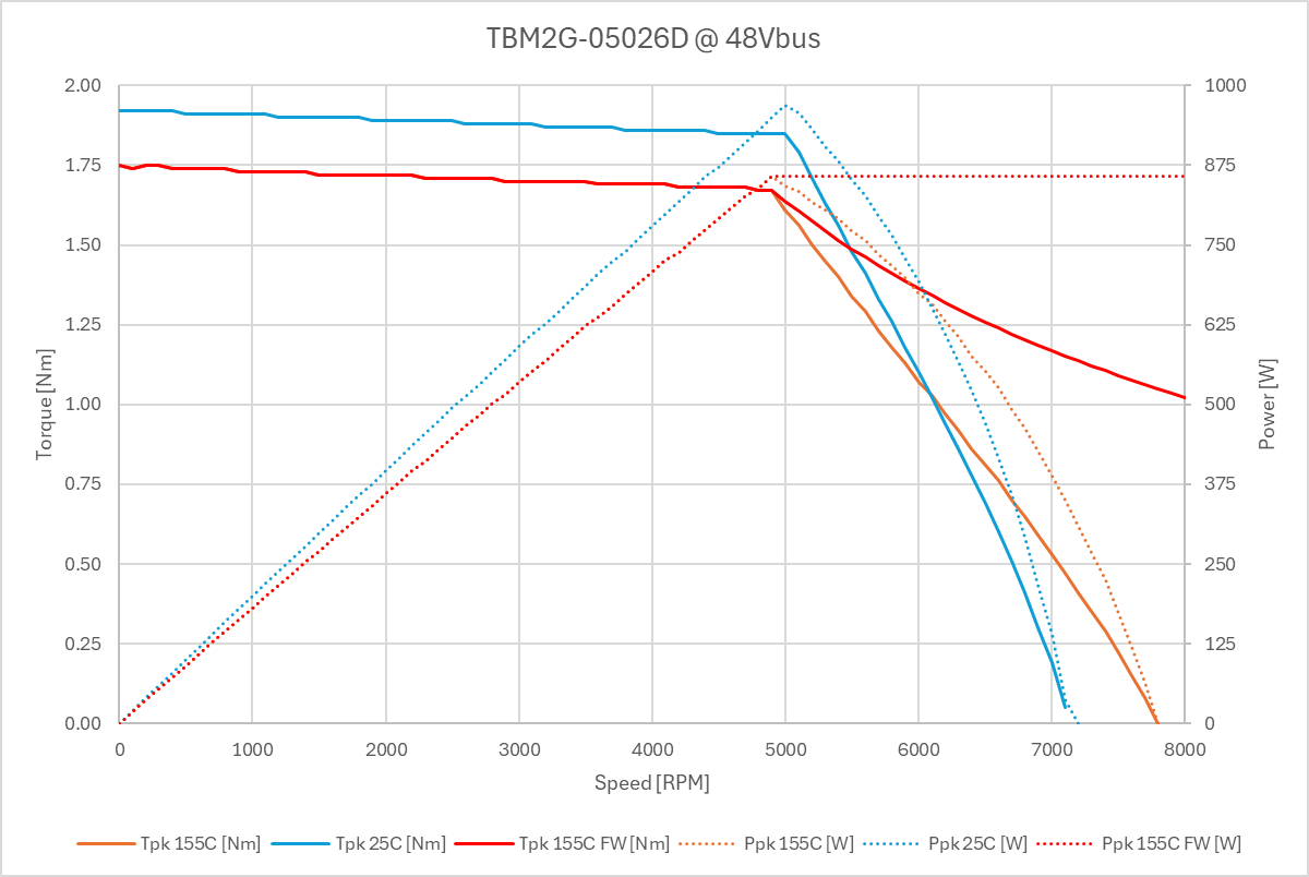
I also added a theoretical curve at 155C with Field Weakening enabled. (I understand it won’t match perfectly to a flat power line, but I was just trying to show the potential.)

I have an external controller that is sending the torque commands and reading feedback from the ODrive, so I have quite a bit of flexibility to change things on the fly. One way I was thinking about accomplishing this temperature compensation was to update the motor model parameters on the fly over CAN since it appears with the latest firmware I might be able to send SDO commands to individual parameters. Is that true? If so, what model parameters should I be looking into changing?

At a minimum I believe I’d want to change:

  • phase_inductance (or ideally motor_model_l_d and motor_model_l_q)
  • phase_resistance
  • torque_constant
  • ff_pm_flux_linkage (maybe? I need to look into how to calculate/measure/acquire this)
  • what else?

For example on what I have for motor parameters right now:
image
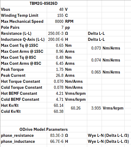
This is what was provided by the manufacturer in their public datasheet (along with some of my calcs). Like I mentioned though, I should be able to get whatever additional information is needed from them.

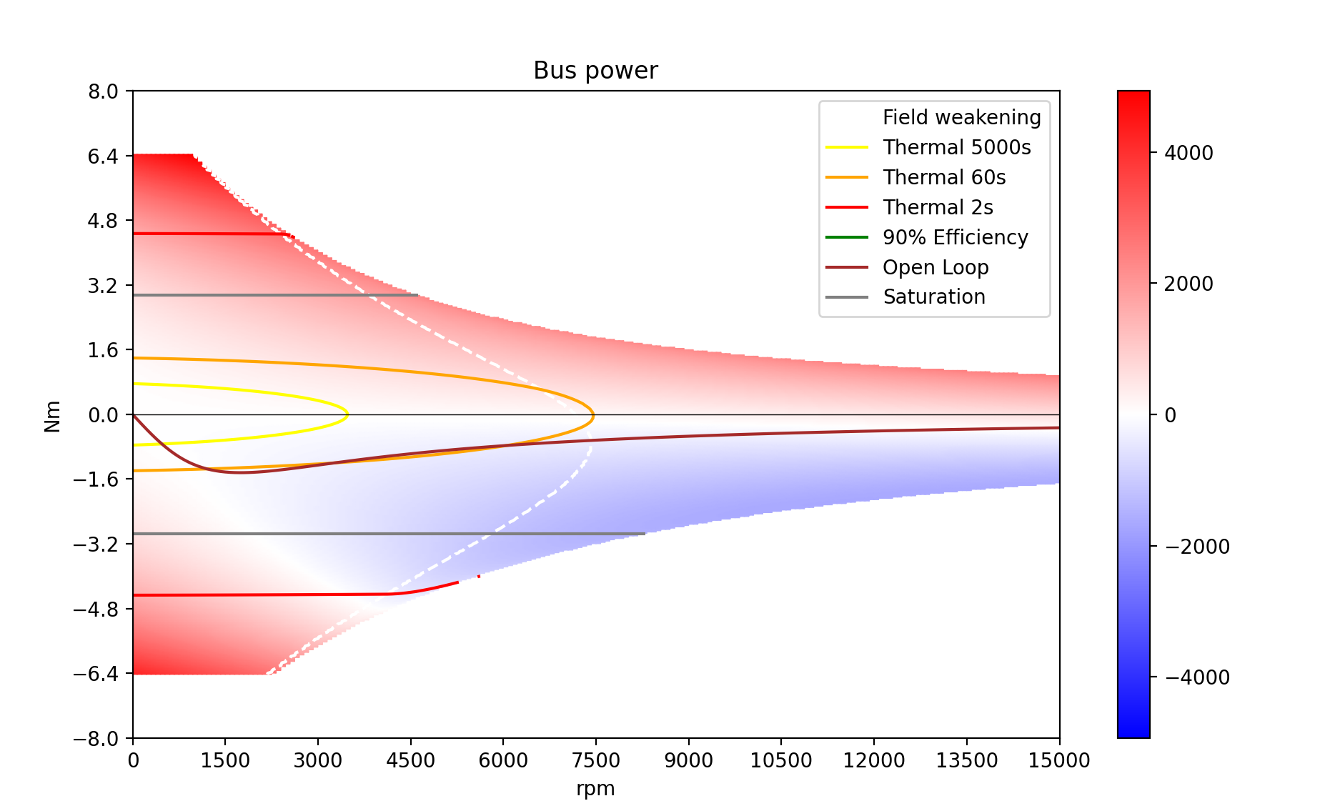
Onto the Field Weakening…

From what I’ve gathered digging around here and in the docs, I’d need to do the following:

  • Set fw_enable
  • Set fw_mod_setpoint to the modulation index the FW controller will control Id to. (any guidelines here? Since I have a Pro, can I set it 0.99, or do I need to go lower?)
  • Set fw_fb_bandwidth. (Any guidelines on starting points, or is this going to be some trial and error? I’d expect I’ll need to do something like set a fixed torque that gets me into field weakening, but not up against the speed limiter, and adjust until mod index is controlled nicely?)

I assume setting accurate motor model motor_model_l_d, motor_model_l_q, and ff_pm_flux_linkage are critical for FW?

What about wL_FF_enable and bEMF_FF_enable, are they worth enabling if I end up getting all the other motor model parameters on point?

Essentially on top of trying to get the most “aggressive”/unfiltered performance out of this motor, I’m looking to be able to produce some usable torque out to 8000RPM, since I will need to operate out there, and without FW, I don’t see how I’ll be able to make it work.

Alright I know that was a lot, but hopefully that lays it all out and you guys can help correct me where I’m wrong and guide me to what I’m after!

Thank you!

Thank you for all the information! This is very helpful.

Quick notes:

Temperature Compensation of the motor model parameters

Interesting. Should be a fairly trivial change. You can’t currently feed this in externally (requires ODrive reboot to apply new torque_constant/inductance/resistance/linkage/etc), but it’s a theoretically straightforward change to allow in real-time; that being said, makes more sense to have an internal mapping from thermistor output.

I assume that this temperature dependence is just from standard NdFeB temperature coefficient? e.g. linear map with temperature?

with the latest firmware I might be able to send SDO commands to individual parameters. Is that true?

Yes!

From what I’ve gathered digging around here and in the docs, I’d need to do the following:
Set fw_enable
Set fw_mod_setpoint to the modulation index the FW controller will control Id to. (any guidelines here? Since I have a Pro, can I set it 0.99, or do I need to go lower?)
Set fw_fb_bandwidth. (Any guidelines on starting points, or is this going to be some trial and error? I’d expect I’ll need to do something like set a fixed torque that gets me into field weakening, but not up against the speed limiter, and adjust until mod index is controlled nicely?)

I am embarrassingly less versed in ODrive’s field weakening, though we do have customers who use it. I can check in internally.

I assume setting accurate motor model motor_model_l_d, motor_model_l_q, and ff_pm_flux_linkage are critical for FW?

Absolutely.

What about wL_FF_enable and bEMF_FF_enable, are they worth enabling if I end up getting all the other motor model parameters on point?

Yes, absolutely.

With a very quick plot from Eelco’s great pypowertrain, it definitely looks like this motor can field weaken okay-ish (please ignore the thermal numbers, I made up values for those and are definitely inaccurate).

I think the biggest thing here is – how much torque do you actually need at 8000 RPM? And at what duty cycle (e.g. how much at continuous, how much at peak, etc)? I am definitely concerned about the amount of Id current needed – these are some strong magnets, and the motor’s current limit is pretty low.

Thank you for such a detailed response!

Good to know that we can’t change those values without a power cycle.

If it would be possible to have those added to the firmware (based on the internal temperature measurement as you suggested), that would be awesome. It is linear as far as I can tell, and yes it appears to be the standard coefficient.

Not sure how you’d want to implement that. I could see something like setting the motor parameters along with the temperature they were measured at, then just selecting a coefficient. That’s probably the easiest. Otherwise the more flexible way would just be a LUT, but not sure how much of a pain that’d be with how the system is setup today.

On the field weakening…I started to play around with it a bit and did run into the typical issue I’ve seen in the past with other controllers where when you remove the torque command it doesn’t actually drop down to 0 (so in this case it appears as the motor keeps on spinning, but the speed just drops a bit). I’d be really curious to hear what you hear back internally on how to set it up properly. I believe this is partially from encoder offset issues, so while it thinks it’s dropped Iq down to 0, some of the Id is actually contributing to the Q-Axis so it keeps on producing torque. There is also the issue of Id being able to produce torque through reluctance, but with an SM motor that should be almost nothing I think…

For flux linkage, I thought I could get that, but turns out the motor manufacturer does not want to disclose that. So that might kill this for now, or at least mean I need to estimate it somehow.

That pypowertrain tool looks awesome! I’m going to have to play around with that a bit!

Honestly, not much, if we could have a reliable 0.5Nm out there I’d be happy.

It’s mostly that with this application we will be jamming full torque to make a position movement (need to unseat intially), then once it gets going we’ll get about halfway there and have to go to a nearly full torque reverse to park it and not overshoot. Given the dynamics of the mechanical system, it’s very non-linear, which is why we are doing the control externally instead of just depending on ODrive’s internal position control. We’ve prototyped this with a much lager motor and it works great, but now we have our custom motor that’s much smaller to fit in the packaging space we had available. Anyways, we’ve seen peak speeds in excess of 7k, so having torque out there to perform the torque reversal to park it will be good to have.

To put overall duty cycle into perspective, we are performing the entire movement in under 30ms. Accelerate from stall, to 7k+, and back down (gently!) to 0RPM at the new position, all within 30ms. We will perform these movements with at least a 1s gap between them. (motor has zero current through it unless the movement is requested) It’s not a known cycle, and most times the events will have minutes between them, but worst case would be a series of maybe 3 events within 5 seconds.

Hence why I’m not too concerned with how many amps we’ll be pumping into it. So long as we don’t demag the motor, I think we’re good.

30ms is definitely a pretty aggressive target, but should be doable. Some other considerations here – I think it would be best to schedule a time to chat and learn more about your application, could you shoot me an email at solomon.greenberg@odriverobotics.com?

For flux linkage, I thought I could get that, but turns out the motor manufacturer does not want to disclose that. So that might kill this for now, or at least mean I need to estimate it somehow.

Not an issue to calculate/characterize!

1 Like

The SimpleFOC sensorless flux observer calculates flux_linkage = 60 / ( _SQRT3 * _PI * _motor.KV_rating * _motor.pole_pairs * 2);
KV is in RPM/volt, so I think it’s mostly just converting to electrical rad/s, but I’m not sure where the sqrt(3) comes from.

We typically estimate flux_linkage = 2/3 * torque_constant / pole_pairs, which is the same as flux_linkage = 5.51328895422 / (pole_pairs * motor_kv). Looks like this is the same equation that SimpleFOC uses. Note though that’s just an estimate, it’s not necessarily the correct result if accuracy is needed.