I use the Odrive S1 to test custom motors i make, i’m currently working on a 4KV motor, quite big and powerfull.
The issue is that with the same power supply set to 24 V and 10A the motor runs at a maximum of 1.2 rps when controlled by a ESC (sensorless and with no way to configure anything) and when controlled by the Odrive i can reach at maximum .9 rps.
Is that expected behavior or might i be configuring it wrong? I had to calculate the specs of the motor myself so i tried playing around with the KV when configuring the motor, but to no efect, the maximum is always 0.9rps
Also its the first time i have to configure a motor as gimbal! The phase resistance is 1.5ohm, i dont know if that might be related
Hi! Yes, the S1 has a 78% modulation depth limit, this is effectively the maximum utilizable percentage of DC bus voltage. This limit will be lifted in a future firmware version.
However, the gimbal mode may be also exacerbating this. You can try running in the HIGH_CURRENT/PMSM_CURRENT_CONTROL mode, or you can enable the wL_FF_enable feedforward term to help compensate for motor inductance. The bEMF_FF_enable term may also work, but it relies on an accurate torque_constant value (which is 8.27/kv, so it relies on an accurate KV value). Happy to give instructions for characterizing the kv experimentally!
1 Like
Thanks a lot for all the information, i’ll test all of it!
I’d really appreciate those instructions if you wouldnt mind!
For now i’m calculating kv like this: i have a comercial motor conected to an odrive spining at a set speed. The comercial motor is attached to the rotor of the tested motor. And with a multimeter i’m reading the voltage generated across two of the phases of the tested motor
The “proper” way here is with an oscilloscope, Oskar showed the methodology here: Project HoverArm - #2 by madcowswe
Very cool post, thanks! I’ll look into getting an osciloscope to test it. Would you expect the results from both methods to stray a lot from each other?
Typically scoping it is the most accurate option, but zooming in I see that’s a true RMS multimeter, so what you had before might work fine!
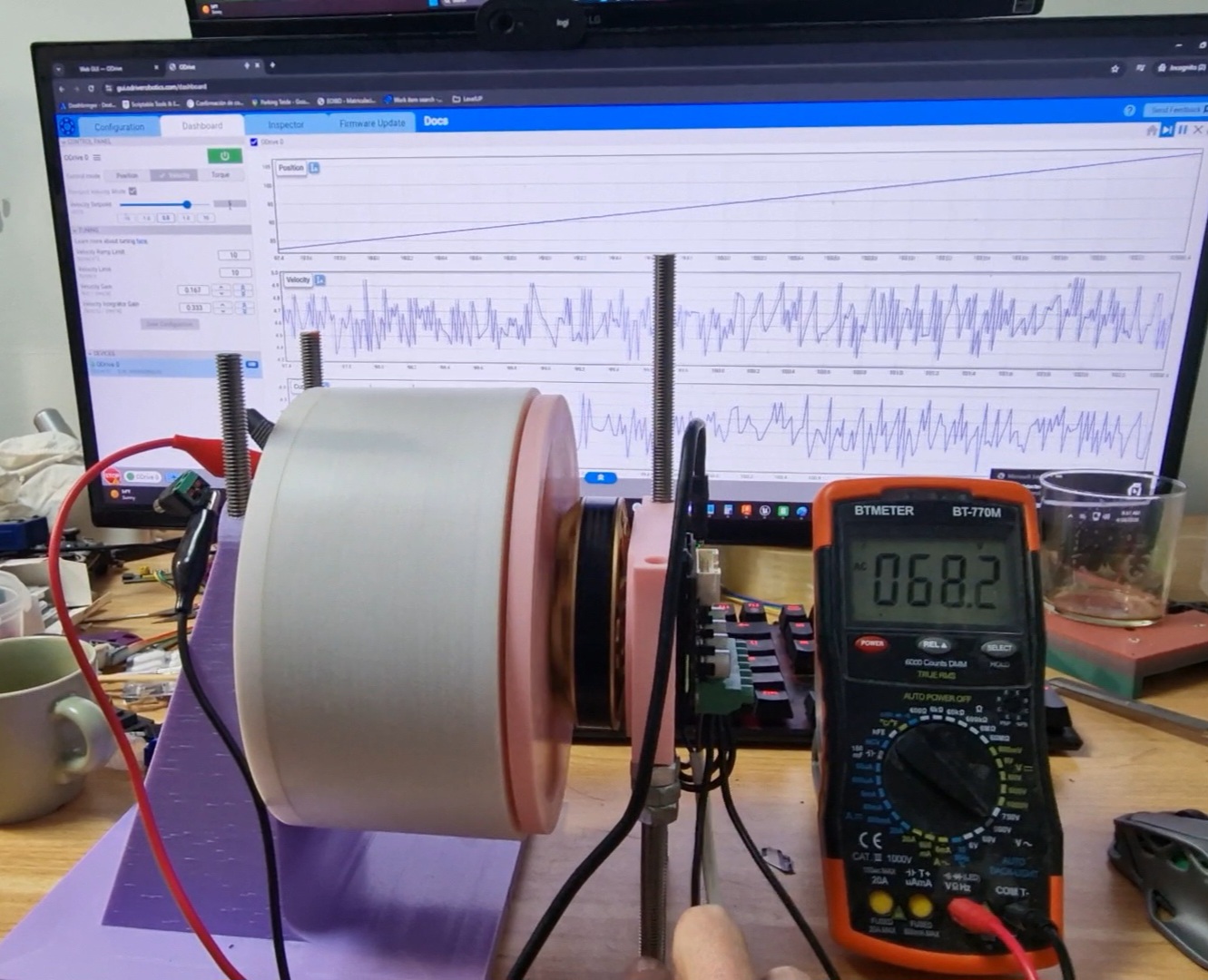
Looks like (zooming in on the GUI screen) you’re spinning at about 4.7 rev/s?
68.2VAC (from the DMM) == 96.44 Vpk. So KV here would be (4.7*60)/96.44 = 2.92 RPM/V.
This seems pretty low, all things considered.
One other way you can do this:
- Setup/configure/calibrate the motor from the ODrive, you could even use the one mounted already and just use the existing magnet mounting, but run wires to your custom motor phase.
- Put the motor in velocity control, tune the gains to be stable.
- Spin the motor at a few different velocity setpoints ranging from about 25-75% of motor’s max free speed.
- At each velocity setpoint, measure
axis0.vel_estimate and axis0.motor.foc.v_current_control_integral_q.
- KV will be vel_estimate * 60 / (sqrt(3) * v_current_control_integral_q)
This will be slightly inaccurate due to load on the motor and other losses, but it’ll get you a general ballpark. In a future firmware update, we’ll have the ability to automatically measure/characterize the motor KT