#include <Arduino.h>
#include “ODriveCAN.h”
// Documentation for this example can be found here:
// Controlling ODrive from an Arduino via CAN — ODrive Documentation 0.6.11 documentation
/* Configuration of example sketch -------------------------------------------*/
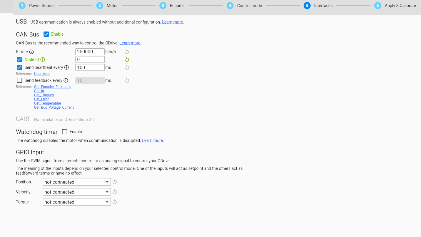
// CAN bus baudrate. Make sure this matches for every device on the bus
#define CAN_BAUDRATE 250000
// ODrive node_id for odrv0
#define ODRV0_NODE_ID 0
// Uncomment below the line that corresponds to your hardware.
// See also “Board-specific settings” to adapt the details for your hardware setup.
// #define IS_TEENSY_BUILTIN // Teensy boards with built-in CAN interface (e.g. Teensy 4.1). See below to select which interface to use.
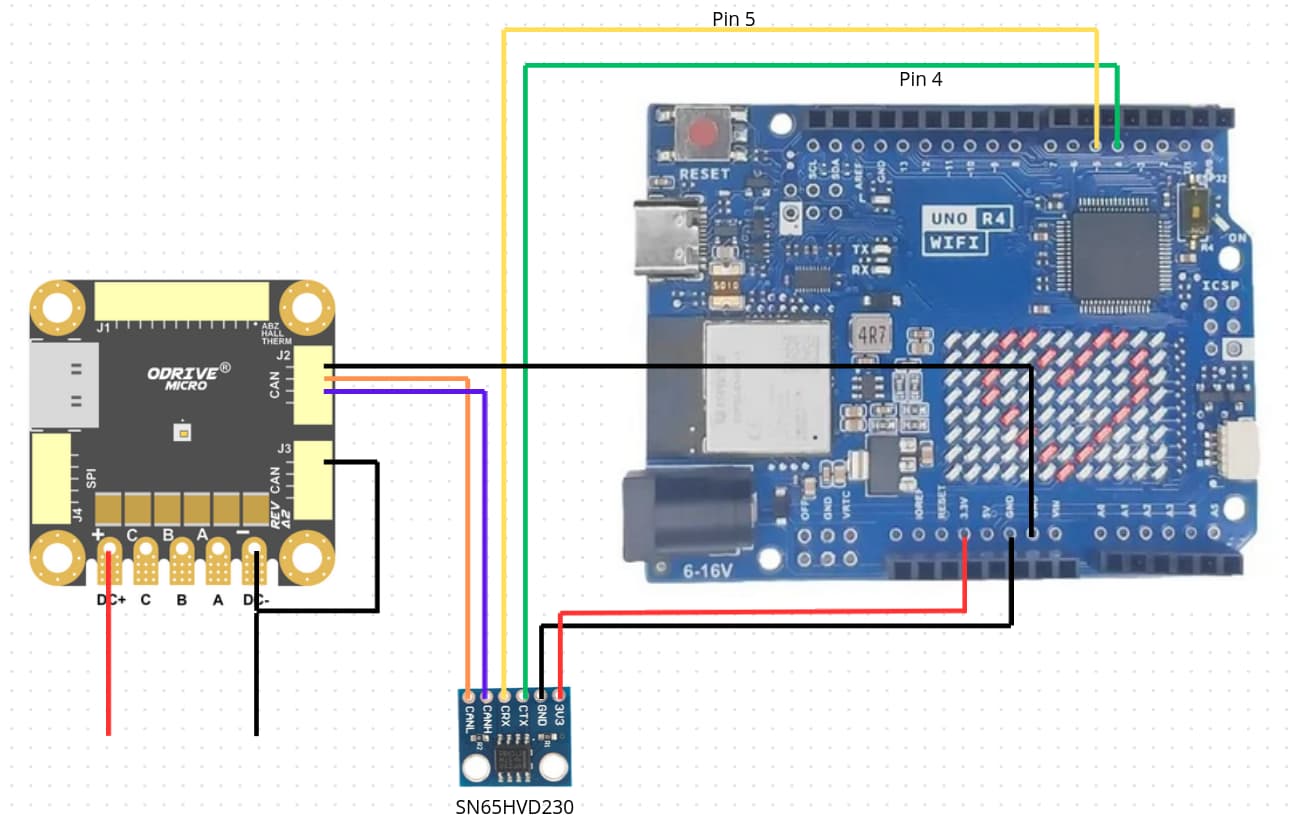
#define IS_ARDUINO_BUILTIN // Arduino boards with built-in CAN interface (e.g. Arduino Uno R4 Minima)
// #define IS_MCP2515 // Any board with external MCP2515 based extension module. See below to configure the module.
/* Board-specific includes ---------------------------------------------------*/
#if defined(IS_TEENSY_BUILTIN) + defined(IS_ARDUINO_BUILTIN) + defined(IS_MCP2515) != 1
#warning “Select exactly one hardware option at the top of this file.”
#if CAN_HOWMANY > 0 || CANFD_HOWMANY > 0
#define IS_ARDUINO_BUILTIN
#warning “guessing that this uses HardwareCAN”
#else
#error “cannot guess hardware version”
#endif
#endif
#ifdef IS_ARDUINO_BUILTIN
// See ArduinoCore-API/api/HardwareCAN.h at master · arduino/ArduinoCore-API · GitHub
// and ArduinoCore-renesas/libraries/Arduino_CAN at main · arduino/ArduinoCore-renesas · GitHub
#include <Arduino_CAN.h>
#include <ODriveHardwareCAN.hpp>
#endif // IS_ARDUINO_BUILTIN
#ifdef IS_MCP2515
// See GitHub - sandeepmistry/arduino-CAN: An Arduino library for sending and receiving data using CAN bus.
#include “MCP2515.h”
#include “ODriveMCPCAN.hpp”
#endif // IS_MCP2515
#ifdef IS_TEENSY_BUILTIN
// See GitHub - tonton81/FlexCAN_T4: FlexCAN (CAN 2.0 / CANFD) Library for Teensy 3.x and 4.0
// clone GitHub - tonton81/FlexCAN_T4: FlexCAN (CAN 2.0 / CANFD) Library for Teensy 3.x and 4.0 into /src
#include <FlexCAN_T4.h>
#include “ODriveFlexCAN.hpp”
struct ODriveStatus; // hack to prevent teensy compile error
#endif // IS_TEENSY_BUILTIN
/* Board-specific settings ---------------------------------------------------*/
/* Teensy */
#ifdef IS_TEENSY_BUILTIN
FlexCAN_T4<CAN1, RX_SIZE_256, TX_SIZE_16> can_intf;
bool setupCan() {
can_intf.begin();
can_intf.setBaudRate(CAN_BAUDRATE);
can_intf.setMaxMB(16);
can_intf.enableFIFO();
can_intf.enableFIFOInterrupt();
can_intf.onReceive(onCanMessage);
return true;
}
#endif // IS_TEENSY_BUILTIN
/* MCP2515-based extension modules -*/
#ifdef IS_MCP2515
MCP2515Class& can_intf = CAN;
// chip select pin used for the MCP2515
#define MCP2515_CS 10
// interrupt pin used for the MCP2515
// NOTE: not all Arduino pins are interruptable, check the documentation for your board!
#define MCP2515_INT 2
// freqeuncy of the crystal oscillator on the MCP2515 breakout board.
// common values are: 16 MHz, 12 MHz, 8 MHz
#define MCP2515_CLK_HZ 8000000
static inline void receiveCallback(int packet_size) {
if (packet_size > 8) {
return; // not supported
}
CanMsg msg = {.id = (unsigned int)CAN.packetId(), .len = (uint8_t)packet_size};
CAN.readBytes(msg.buffer, packet_size);
onCanMessage(msg);
}
bool setupCan() {
// configure and initialize the CAN bus interface
CAN.setPins(MCP2515_CS, MCP2515_INT);
CAN.setClockFrequency(MCP2515_CLK_HZ);
if (!CAN.begin(CAN_BAUDRATE)) {
return false;
}
CAN.onReceive(receiveCallback);
return true;
}
#endif // IS_MCP2515
/* Arduinos with built-in CAN */
#ifdef IS_ARDUINO_BUILTIN
HardwareCAN& can_intf = CAN;
bool setupCan() {
return can_intf.begin((CanBitRate)CAN_BAUDRATE);
}
#endif
/* Example sketch ------------------------------------------------------------*/
// Instantiate ODrive objects
ODriveCAN odrv0(wrap_can_intf(can_intf), ODRV0_NODE_ID); // Standard CAN message ID
ODriveCAN* odrives = {&odrv0}; // Make sure all ODriveCAN instances are accounted for here
struct ODriveUserData {
Heartbeat_msg_t last_heartbeat;
bool received_heartbeat = false;
Get_Encoder_Estimates_msg_t last_feedback;
bool received_feedback = false;
};
// Keep some application-specific user data for every ODrive.
ODriveUserData odrv0_user_data;
// Called every time a Heartbeat message arrives from the ODrive
void onHeartbeat(Heartbeat_msg_t& msg, void* user_data) {
ODriveUserData* odrv_user_data = static_cast<ODriveUserData*>(user_data);
odrv_user_data->last_heartbeat = msg;
odrv_user_data->received_heartbeat = true;
}
// Called every time a feedback message arrives from the ODrive
void onFeedback(Get_Encoder_Estimates_msg_t& msg, void* user_data) {
ODriveUserData* odrv_user_data = static_cast<ODriveUserData*>(user_data);
odrv_user_data->last_feedback = msg;
odrv_user_data->received_feedback = true;
}
// Called for every message that arrives on the CAN bus
void onCanMessage(const CanMsg& msg) {
Serial.println(“MSG”);
for (auto odrive: odrives) {
onReceive(msg, *odrive);
}
}
void setup() {
Serial.begin(115200);
// Wait for up to 3 seconds for the serial port to be opened on the PC side.
// If no PC connects, continue anyway.
for (int i = 0; i < 30 && !Serial; ++i) {
delay(100);
}
delay(200);
Serial.println(“Starting ODriveCAN demo”);
// Register callbacks for the heartbeat and encoder feedback messages
odrv0.onFeedback(onFeedback, &odrv0_user_data);
odrv0.onStatus(onHeartbeat, &odrv0_user_data);
// Configure and initialize the CAN bus interface. This function depends on
// your hardware and the CAN stack that you’re using.
if (!setupCan()) {
Serial.println(“CAN failed to initialize: reset required”);
while (true); // spin indefinitely
}
Serial.println(“Waiting for ODrive…”);
while (!odrv0_user_data.received_heartbeat) {
pumpEvents(can_intf);
}
Serial.println(“found ODrive”);
// request bus voltage and current (1sec timeout)
Serial.println(“attempting to read bus voltage and current”);
Get_Bus_Voltage_Current_msg_t vbus;
if (!odrv0.request(vbus, 1000)) {
Serial.println(“vbus request failed!”);
while (true); // spin indefinitely
}
Serial.print("DC voltage [V]: ");
Serial.println(vbus.Bus_Voltage);
Serial.print("DC current [A]: ");
Serial.println(vbus.Bus_Current);
Serial.println(“Enabling closed loop control…”);
while (odrv0_user_data.last_heartbeat.Axis_State != ODriveAxisState::AXIS_STATE_CLOSED_LOOP_CONTROL) {
odrv0.clearErrors();
delay(1);
odrv0.setState(ODriveAxisState::AXIS_STATE_CLOSED_LOOP_CONTROL);
// Pump events for 150ms. This delay is needed for two reasons;
// 1. If there is an error condition, such as missing DC power, the ODrive might
//    briefly attempt to enter CLOSED_LOOP_CONTROL state, so we can't rely
//    on the first heartbeat response, so we want to receive at least two
//    heartbeats (100ms default interval).
// 2. If the bus is congested, the setState command won't get through
//    immediately but can be delayed.
for (int i = 0; i < 15; ++i) {
  delay(10);
  pumpEvents(can_intf);
}
}
Serial.println(“ODrive running!”);
}
void loop() {
pumpEvents(can_intf); // This is required on some platforms to handle incoming feedback CAN messages
// Note that on MCP2515-based platforms, this will delay for a fixed 10ms.
//
// This has been found to reduce the number of dropped messages, however it can be removed
// for applications requiring loop times over 100Hz.
float SINE_PERIOD = 2.0f; // Period of the position command sine wave in seconds
float t = 0.001 * millis();
float phase = t * (TWO_PI / SINE_PERIOD);
odrv0.setPosition(
sin(phase), // position
cos(phase) * (TWO_PI / SINE_PERIOD) // velocity feedforward (optional)
);
// print position and velocity for Serial Plotter
if (odrv0_user_data.received_feedback) {
Get_Encoder_Estimates_msg_t feedback = odrv0_user_data.last_feedback;
odrv0_user_data.received_feedback = false;
Serial.print(“odrv0-pos:”);
Serial.print(feedback.Pos_Estimate);
Serial.print(“,”);
Serial.print(“odrv0-vel:”);
Serial.println(feedback.Vel_Estimate);
}
}