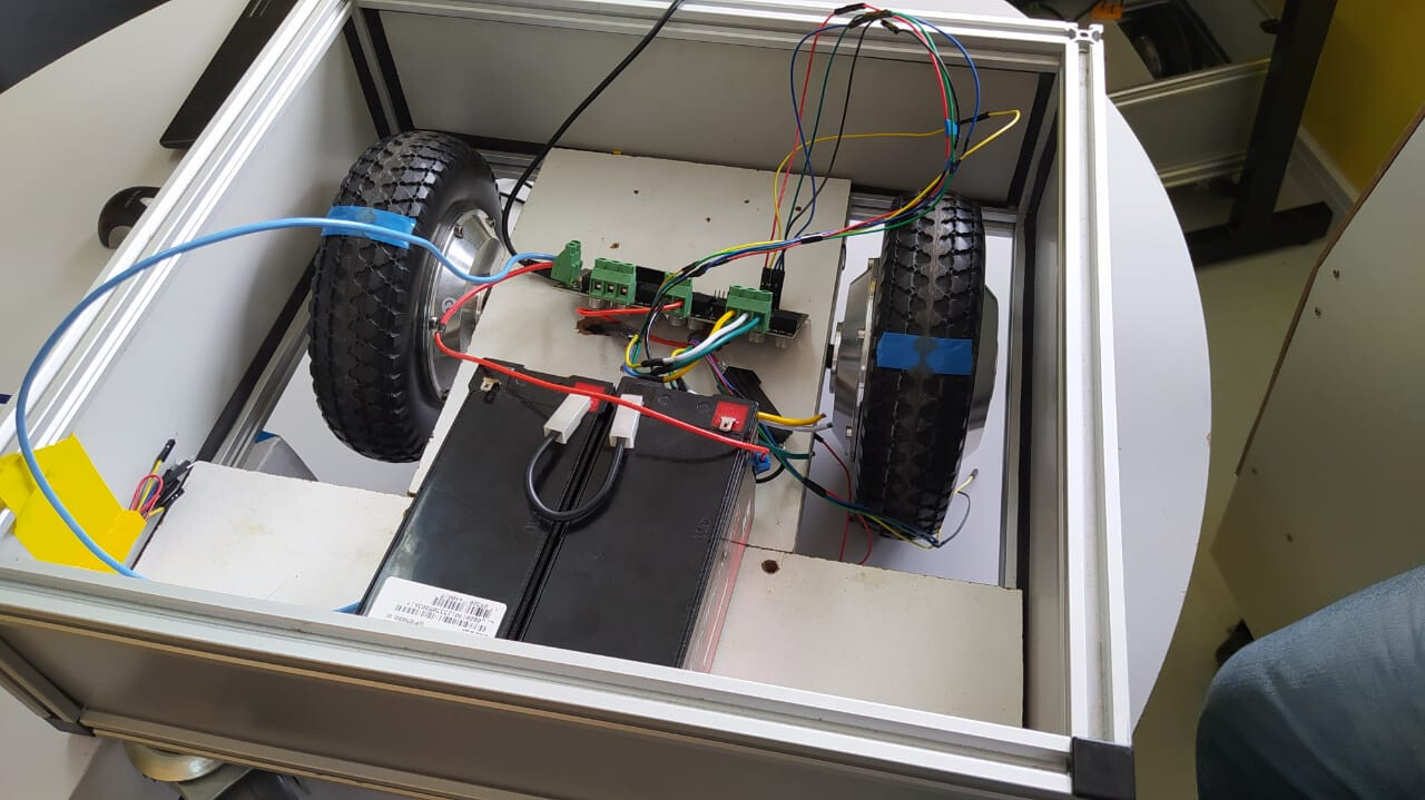
My ODrive arrived today, and I was really eager to use her, so I immediately tried putting her to work here - however, I’ve been having a problem.
I have two sets of hoverboard motors, one with a planetary gearbox, and other without it. I tried to use the ODrive as a hoverboard, as it has a whole section for it in the documentation. However, the one with a planetary gearbox returned me four errors when I tried to check the status of the encoder object.
When I tried to just move the wheels, I got nothing, and the wheel didn’t spin.
Moving to the other platform, with regular motors, I then got two errors with the encoder - however, after rebooting the ODrive, all the errors disappeared, and the wheels worked as they should.
I’ve tried the same with the other platform, but to no avail. I managed to get from four to two errors, but nothing that would make my motor work.
Does anybody know the reason? Is it because of the planetary gearboxes, or is it for some reason I missed to understand? The parameters I’ve been using are all the same noted in the hoverboard page.
Where is the encoder? Is it on the motor side, or the wheel side of the gearbox?
If it’s on the wheel side, then you cannot use it as primary feedback (motor commutation). If you also have Hall sensors, then you can use that for motor commutation instead.
It is possible to use two encoders, one for commutation and the other for positioning, but unfortunately ODrive only has two inputs for incremental encoders and Hall sensors - one for each axis.
Maybe you could mount an absolute magnetic encoder on the inside of your box, and use that for load feedback?
I know the devs were working on code to allow this, but I don’t know if it’s ready yet.
Ok. Hall encoders are always on the motor side. Most likely, you have the CPR set wrong. Remember that it needs to be per motor revolution, not per wheel revolution. If you can’t see the motor, try dividing by the gear ratio.
Probably, cpr should be set the same as your other motors i.e. pole_pairs * 6
Hall “encoders” are an extremely low resolution encoder that uses the magnets of the motor itself.
It’s possible to make a really crude BLDC controller using nothing more than these Hall sensors, a few discrete logic gates and a mosfet bridge. But more advanced servo drives like ODrive can achieve much better control performance if they have high resolution encoder feedback.
If you needed very tight control then you could use a magnetic encoder on the wheel, but tbh if you only have Hall sensors on the motor itself, it’s not going to add much.
So you mean we should look out for a better encoder so it can work? The ones without the planetary worked fine just with the Hall, so I’m a bit confused on why the other ones aren’t working. If we need to change the encoders, which type of encoders should we get? (Apologies, I’ve never really dealt with encoders)
Is there a way to see which errors we’re getting? I see we’re getting 0x02 errors and the wheels aren’t turning, but I don’t know which specific errors are these two.
Alright, I’ve made more tests here, and turns out that the wheels work now (I don’t really know why - I haven’t really changed any configurations)… but only one at the time.
At the time, I was testing only one wheel, on M0 - it didn’t work then, now it did for some reason. However, when trying to use the wheel on M1, it doesn’t turn, at all. We tried changing the wheels, putting the one that was on M1 in M0 and vice versa, but the problem keeps the same - no matter the wheel, the one in M0 works, and the one in M1 doesn’t.
We’re a bit stumped on what to do, but now we’re certain that the planetary gear probably has nothing to do with the problem. Could it be a problem with our ODrive? I’ve executed the same steps in the hoverboard guide to run the other wheel, but changing all axis0 to axis1.
I’m very lost here, and if anyone knows anything that can help, I’d be really thankful!
Update - We’ve checked the voltage in each motor phase in the ODrive. The ones in the M0 all have 11V, while the ones in M1 all have 1.8V, no matter the motor that’s connected in there.
Update 2 - Now the motors are taking turns. Sometimes only M1 works, sometimes only M0 works. It seems completely random, and there wasn’t a single time where they worked at the same time.
Can you check your errors with the dump_errors command?
i.e. dump_errors(odrv0) to list them, or dump_errors(odrv0, True) to list them AND clear them
If you are getting ILLEGAL_HALL_STATE for example, then probably you need to add some filter capacitors to your encoder inputs. Usually 22nF between each input and GND works well.
a 22nF capacitor between A/B/Z and GND, then? I’ll try to get into that and see if it works.
However, that error appears only if both axis0 and axis1 are configurated. If only one of them is configurated, we get AXIS_ERROR_ENCODER_FAILED / ENCODER_ERROR_CPR_POLEPAIRS_MISMATCH instead. Do you know the reason why?
You may have two separate problems. 1 is a noise issue and causes invalid hall state. The other is that your calculation for pole pairs or CPR may be wrong.
We’ve configured here with the 22nF capacitors, using six of them, putting one for each signal between them and the GND, but nothing - it still doesn’t work properly, and it still gives the same error =/
But the wheels do work - only one at the time, instead of them both together. Considering that they spin, is it still a CPR problem?
Once again, thanks!
Update - We talked here, and we thought that maybe the way we configured the capacitors could be lowering its power - we used them on a breadboard, instead of soldering the capacitors or something close to that. Should we solder the capacitors to the board? That idea came across here, but we’re scared of damaging the board.
Or maybe using two capacitors for each would help?
Update 2 - Alright, we’ve soldered the capacitors into the board, but, still, nothing. We keep getting the 0x0002 error in one of the wheels when checking the encoder. =/
At this point, i would put an oscilloscope on the pins to see if there’s any noise, or double check your settings. What is your encoder.config.cpr and your motor.config.pole_pairs?
We put the same as the ones in the guide - CPR is 90, pole_pairs is 15. We’ve been trying that and that configuration runs with only one motor, but not with two.
We’ll try to see if we can find an osciloscope to put it in, then!
Sorry for the late response, but we tried more many times this month, reconfiguring paramenters, getting new wheels to test - because the old ones were actually busted -, all kinds of things, but still, nothing. We can’t get the two wheels running at the same time, only one at a time.
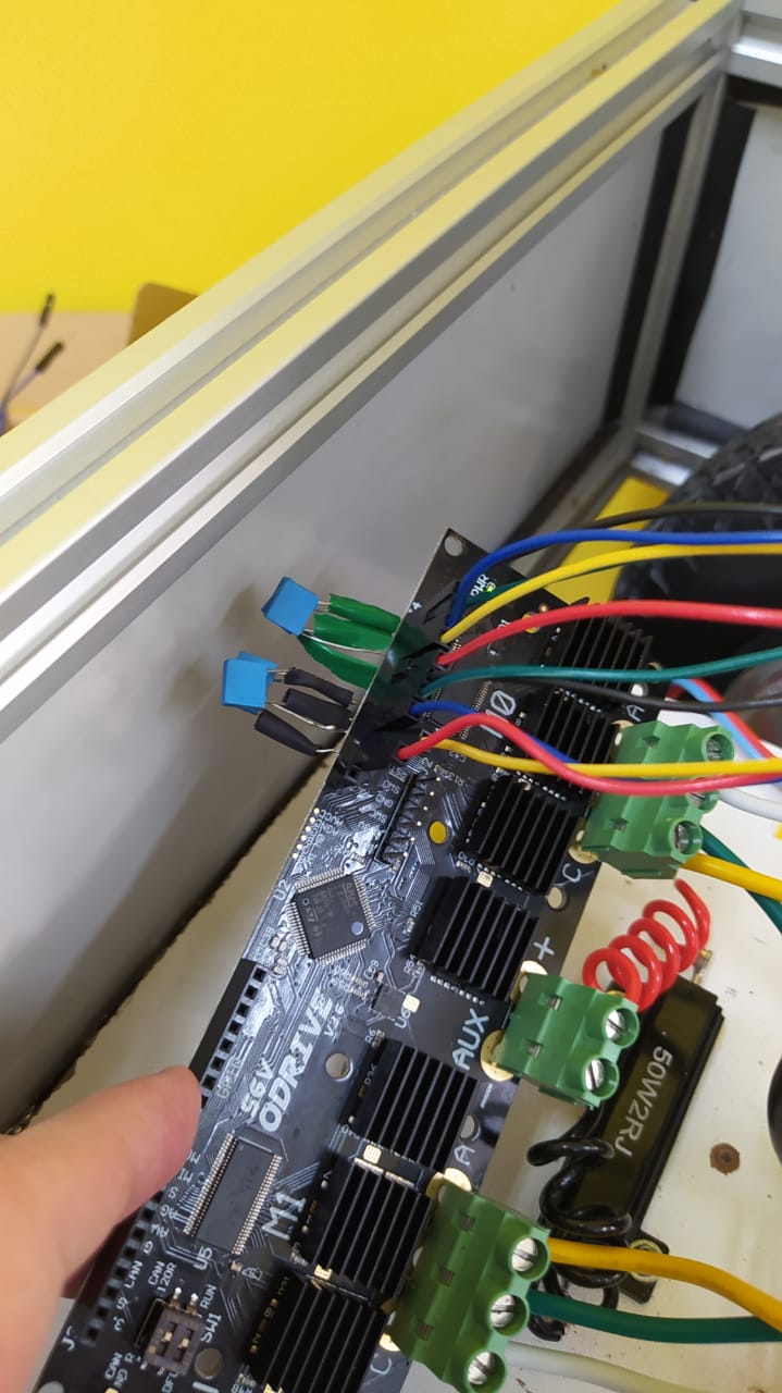
We’re looking for an osciloscope to try to see if there’s any noise, then, now. In which connections should we try to monitor the state of the signal?
Alright! We’ve tested the ABZ pins in both wheels.
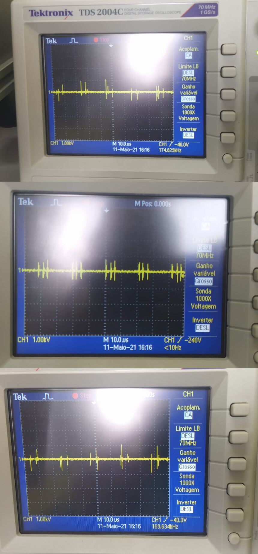
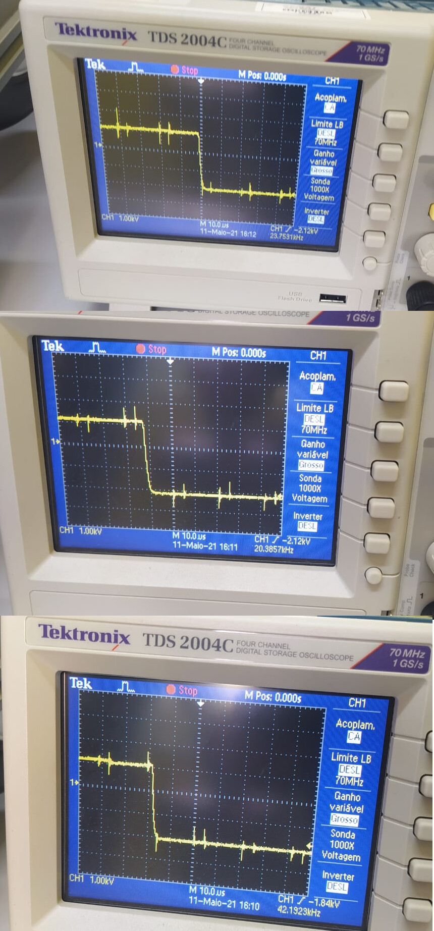
As I said before, every time we test, only one wheel works, and the other doesn’t - most of times, it’s the first wheel we set up. So we tested again - and, as expected, only one wheel worked -, and got the results for the two wheels -
This is what we got for the wheel that wasn’t working:
I am new to this stuff and have had similar issues. I have standard BLDC motors will Hall sensors and the only way i could get it to work was increasing the scanning distance of the sensor . Try increasing the parameter “odrv0.axis0.encoder.config.calib_scan_distance = 150” . This got me going with my 7 pole motor to produce 42 counts per rev. Easy to check the hall sensor output by using the command “odrv0.axis0.encoder.shadow_count” to display the total pulses per rev or part rev. Yu just have to keep turning your motor by hand then enter the shadow count again.
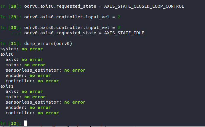
I am having similar problem. axis1 (motor 1) spins very well but axis0 (motor 0) does not run after putting it in closed loop mode. The encoder polarity calibration is successful but each time I try to run the encoder offset calibration, it will return error. I ran the odrvo.clear_errors() command and it returned no error as shown in the screenshot below. However, the axis0 does not spin when i put it in closed loop control mode. Can someone please help me out. I have spent a couple of days trying to figure it out but no good result yet.