Odrive Pro CAN-bus shows error BUS_OFF

Hi everyone,

I’ve been struggling with a CAN communication issue on my ODrive Pro and can’t seem to get it working. I’m hoping someone here has seen this before.
I always get the can error BUS_OFF.

Configuration applied

odrv = odrv0
odrv.config.dc_bus_overvoltage_trip_level = 56
odrv.config.dc_bus_undervoltage_trip_level = 10.5
odrv.config.dc_max_positive_current = math.inf
odrv.config.dc_max_negative_current = -math.inf
odrv.axis0.config.motor.motor_type = MotorType.PMSM_CURRENT_CONTROL
odrv.axis0.config.motor.pole_pairs = 8
odrv.axis0.config.motor.torque_constant = 0.827
odrv.axis0.config.motor.current_soft_max = 10
odrv.axis0.config.motor.current_hard_max = 23
odrv.axis0.config.motor.calibration_current = 3
odrv.axis0.config.motor.resistance_calib_max_voltage = 3
odrv.axis0.config.calibration_lockin.current = 3
odrv.axis0.motor.motor_thermistor.config.enabled = False
odrv.axis0.controller.config.control_mode = ControlMode.VELOCITY_CONTROL
odrv.axis0.controller.config.input_mode = InputMode.VEL_RAMP
odrv.axis0.controller.config.vel_limit = 10
odrv.axis0.controller.config.vel_limit_tolerance = 1.2
odrv.axis0.config.torque_soft_min = -math.inf
odrv.axis0.config.torque_soft_max = math.inf
odrv.axis0.trap_traj.config.accel_limit = 10
odrv.axis0.controller.config.vel_ramp_rate = 10
odrv.can.config.protocol = Protocol.SIMPLE
odrv.can.config.baud_rate = 250000
odrv.axis0.config.can.node_id = 0
odrv.axis0.config.can.heartbeat_msg_rate_ms = 100
odrv.axis0.config.can.encoder_msg_rate_ms = 10
odrv.axis0.config.can.iq_msg_rate_ms = 0
odrv.axis0.config.can.torques_msg_rate_ms = 0
odrv.axis0.config.can.error_msg_rate_ms = 0
odrv.axis0.config.can.temperature_msg_rate_ms = 0
odrv.axis0.config.can.bus_voltage_msg_rate_ms = 1000
odrv.axis0.config.enable_watchdog = False
odrv.axis0.config.encoder_bandwidth = 100
odrv.hall_encoder0.config.enabled = True
odrv.axis0.config.load_encoder = EncoderId.HALL_ENCODER0
odrv.axis0.config.commutation_encoder = EncoderId.HALL_ENCODER0
odrv.config.enable_uart_a = False

The problem

The ODrive Inspector always shows error = BUS_OFF and n_restarts counts up rapidly.

What I have already tried

  • CAN baud rate set to 250000 b/s, protocol SIMPLE, node ID 0 (as above)

  • Wiring checked: CAN-Hi, CAN-Lo, GND — GND is also tied to power GND

  • CAN Analyser V8.0 sees no messages

  • Arduino Nano with MCP2515 module (code from the official guide) also sees no messages

  • Line resistance between CAN-Hi and CAN-Lo: 60 Ω

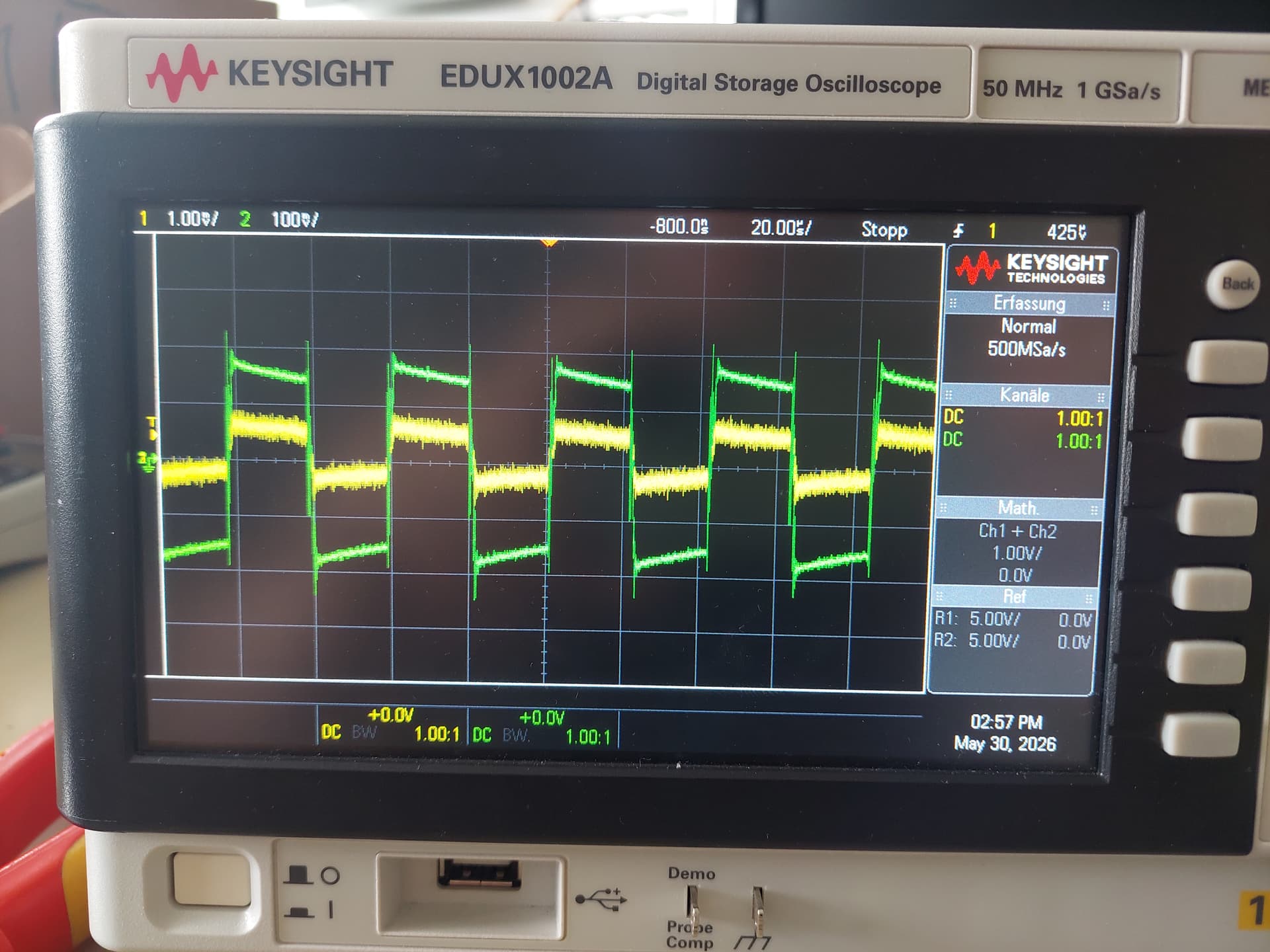
  • Oscilloscope shows small square-wave signals when the ODrive Pro is alone on the bus; the internal termination resistor is enabled

  • Arduino Nano sending messages in 10 ms intervals with ODrive baud rate set to auto — ODrive does not detect the baud rate

  • CAN Analyser V8.0 does receive the Arduino Nano messages when all three devices (MCP2515, ODrive, CAN Analyser) are on the bus together

  • Tried all available baud rates on the ODrive

  • Tried different node IDs: 1, 13, 63

  • Data baud rate left at default (1 Mb) and also set to 250000 b/s

  • Firmware updated to 0.6.12

  • Configuration attempted via WebGUI and via odrivetool
Any ideas what might be going on? Is the ODrive Pro simply not transmitting at all, or is there something fundamentally wrong with how I have it configured?

Thanks in advance!
Hi! Apologies for the delay in my response.

That CAN waveform looks super sketchy, definitely looks like the motor switching noise AC coupling into CAN, which makes me think it’s a grounding issue. Would you mind sending a few pictures of how everything’s wired up?

Hi,

We are currently investigating an issue with the CAN communication on our ODrive Pro boards.

The boards power up normally, and USB communication is working correctly. The motors are functional, but we are not receiving heartbeat messages over CAN. We observed that can.error reports BUS_OFF, and can.n_restarts continuously increases.

At this point, we suspect that the CAN module/transceiver may have been damaged, which is why no heartbeat messages are being transmitted.

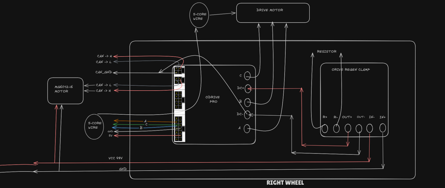
Our CAN wiring was as follows:

  • CANH connected to the controller CANH.
  • CANL connected to the controller CANL.
  • CAN_GND connected to the DC- terminal (48 V negative).
  • The Raspberry Pi side uses an isolated CAN receiver, and its CAN_GND is also referenced to the same DC- terminal.

With the board powered and no external CAN devices connected, we measured:

  • CANH to CAN_GND ≈ 0 V
  • CANL to CAN_GND ≈ 0 V

and the board still enters the BUS_OFF state with can.n_restarts continuously increasing.

Few following questions on this:

  1. How likely is it that the CAN transceiver/module has been damaged?
  2. Does this behavior indicate a failure of the CAN transceiver itself or the isolated CAN power circuitry?
  3. Are there any recommended measurements or diagnostics to confirm whether the CAN hardware is damaged?
  4. Is there a recovery procedure, or would hardware repair/replacement be required?

Thank you.

Hi! What’s the measured resistance between CANH and CANL? And would you mind sharing some pictures of your wiring? And are you powering the board just over USB, or from the DC+ input? By default, the Pro requires power over DC+/DC- for the CAN circuitry to come online.

It’s pretty hard to kill the transceiver on a Pro – likely this is just a wiring or configuration issue.


The measured resistance between CANH and CANL is approximately 61 Ω.

We are using three ODrive Pro controllers on a 3-wheel vehicle: one for the drive wheels and one for steering. Initially, we tested each wheel and ODrive individually, and all of them were working correctly over CAN.

The issue appeared only when all three ODrives were powered and connected together on the vehicle. In that configuration, only one ODrive continued sending heartbeats visible on candump can0 , while the other two stopped responding and did not transmit any heartbeat messages. At that point, we started suspecting possible damage to the CAN transceiver or another hardware component.

Unfortunately, we lost a total of four boards during our troubleshooting. In the first occurrence, the front and left wheel ODrives stopped responding on CAN. In the second occurrence, the left and right wheel ODrives stopped responding. This repeated behavior is what led us to suspect a hardware-related issue rather than a simple configuration problem.

I will also share pictures of the wiring setup. The boards were powered through the DC+ and DC− inputs, not only via USB.

And front odrive as node ID:0,left as node ID:2,right as node ID:4

Hi! Thanks for all the details, and apologies for the delay in my response.

Just to confirm, each ODrive had a tie between CAN_GND and DC-? If CAN_GND is connected between each ODrive, there should only be a single tie for the overall system between CAN_GND and DC- – this sets the GND reference of the CAN bus, so typically you’d do it at your power distribution terminal / busbar / battery.

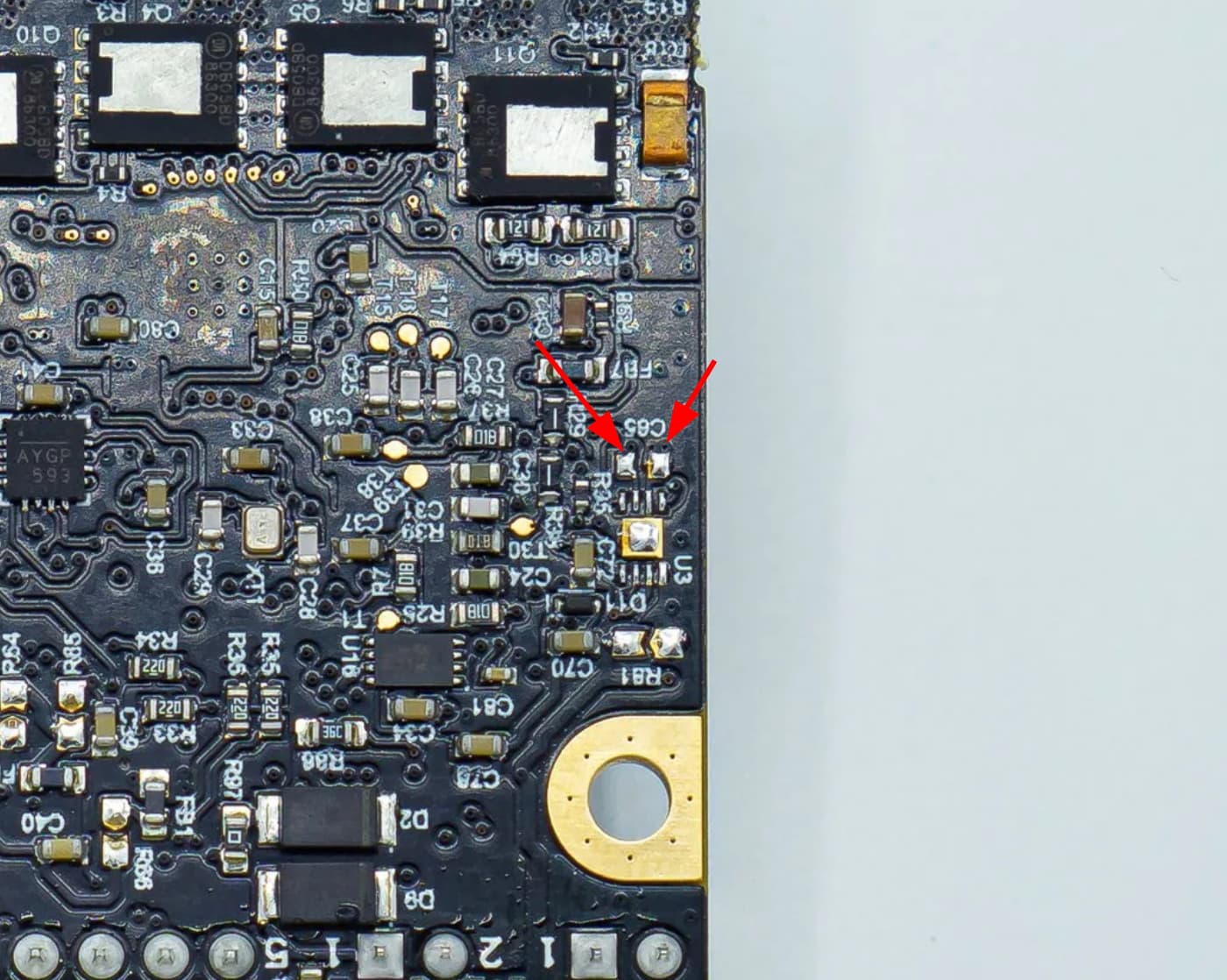
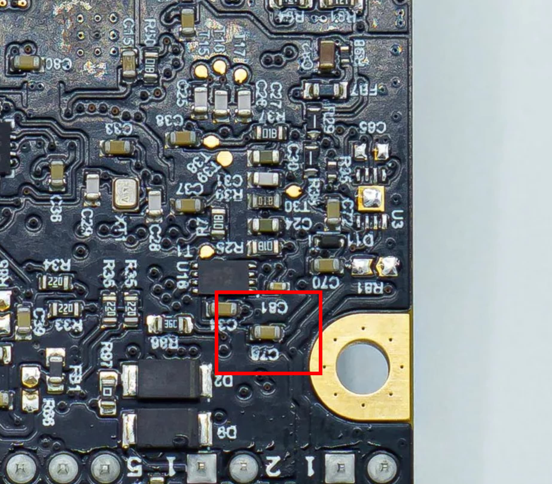
All that being said, I’m generally pretty surprised any of this could’ve killed the CAN transceiver. Was anything on the bus damaged? Would you mind (while the ODrive is powered and connected over CAN) measuring the voltage between these two pads? It should be 5V