I’m troubleshooting an issue with my ODrive Pro where the reported DC bus voltage does not match the voltage measured directly at the power terminals. I’m hoping to identify the cause and determine whether this is a hardware issue or something that can be fixed.
Symptoms
My ODrive Pro is supplied with 24 V DC, measured directly across the DC+ and DC− solder joints using a multimeter. The measured voltage is 24 V, but vbus_voltage in the ODrive GUI consistently reports approximately 4.8–5.4 V. The controller consequently triggers an active DC_BUS_UNDER_VOLTAGE error. The undervoltage trip threshold is set to its default value of 10.5 V.
The wiring and measurement points have been verified, and this setup previously worked correctly.
Troubleshooting performed
- Verified the power supply voltage: I measured 24 V directly across the ODrive Pro’s DC+ and DC− power terminals while observing
vbus_voltage in the GUI at the same time.
- Compared GUI and UART readings: I previously read
vbus_voltage through UART using an ESP32. It reported the same incorrect value as the GUI, suggesting that this is not simply a GUI display issue.
- Tested with only USB-C connected: I disconnected the 24 V supply and all other system connections, leaving only the computer connected to the ODrive through USB-C via a ground-loop isolator. In this state, I measured 0.949 V across DC+ and DC−, while
vbus_voltage continued to report approximately 4.8–5.4 V.
- Updated the firmware repeatedly: Updating through the GUI did not resolve the issue.
- Reinstalled the firmware through legacy DFU: I successfully used
odrivetool legacy-dfu to reinstall firmware version 0.6.12-1, explicitly selecting ODrive Pro. The incorrect voltage reading persisted after the reinstall.
Current assessment
Since the discrepancy persists after reinstalling the firmware, I suspect a possible problem with the DC bus voltage sensing circuit, its connection to the ADC, or another part of the measurement chain. However, I have not yet confirmed the root cause.
I’m particularly interested in determining whether this is a known issue with the ODrive Pro and how to diagnose it at the hardware level. I would appreciate guidance on locating the DC bus voltage sensing circuit, identifying the relevant test points or components, and checking whether the fault is in the sensing circuit or the ADC measurement path.
If this points to a hardware defect, I’d also appreciate advice on repair options.
Thank you for your help!
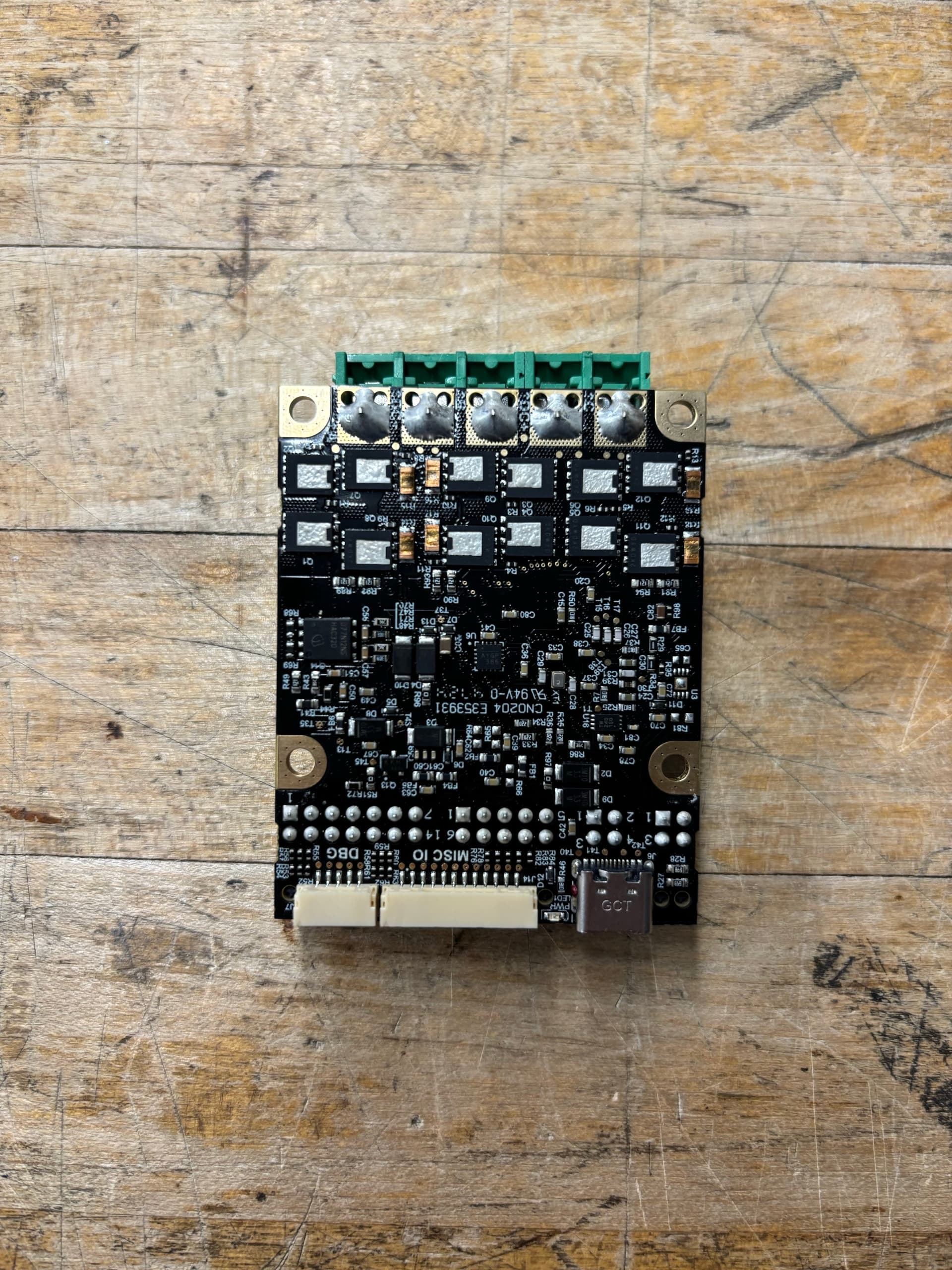
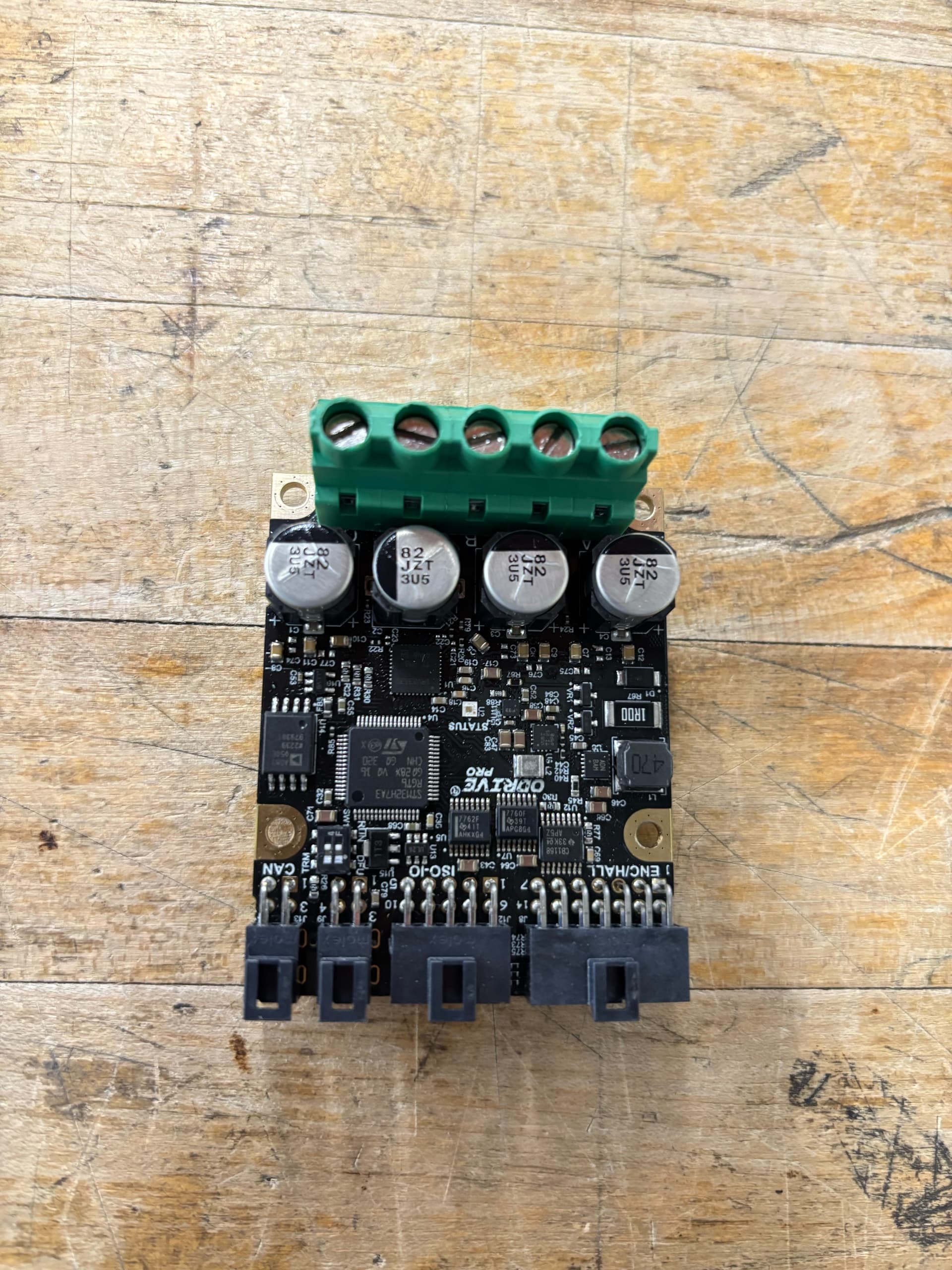
Hi! Thanks for reaching out, and for the detailed description. Not a known defect, it does sound like a possible hardware issue. Did the Pro have this issue out of the box, or did it happen after some use? Could you send some pictures of the top/bottom of the board?
Hi! Thanks for the reply. I’ve attached pictures of both the top and bottom of the board.
The ODrive Pro had been working correctly before the issue occurred. We were running it at 24 V with a velocity setpoint of 1 rev/s. We were performing tests, and at one point, when we started another test after modifying our ESP32 code, the DC_BUS_UNDER_VOLTAGE error appeared. We’re not entirely sure what caused it, as we didn’t make any intentional changes to the power supply or motor command that should have damaged the drive.
We were using a regen clamp with a 50 W, 2 Ω resistor. At the time the issue appeared, the drive was operating at only 24 V and 1 rev/s, so we wouldn’t expect these operating conditions to have caused a component to fail. There was no unusual smell, visible damage, or other obvious sign of a hardware failure.
To help isolate the issue, we are currently running the same system with an ODrive S1 as a temporary replacement. The S1 correctly measures the DC bus voltage, and the rest of our circuit works as expected. However, the S1 limits our motor’s performance, which is why we would like to get the Pro working again.
Gotcha, thanks for the pictures!
I totally agree that your use case shouldn’t have had any risk whatsoever of failure.
Quick test – when powered over USB, and from ODrivetool or the GUI, what does vbus_voltage and axis0.motor.fet_thermistor.temperature show? The former should be 0-2V and the latter should be around your ambient room temperature plus board quiescent temperature rise – maybe 25-45 C. You can also repeat the test when powered from e.g. 24V.
That’ll help bisect a failing analog rail / ADC from just a blown bus voltage sense divider.
Thanks for the suggestions. I performed both tests, with only the USB-C cable connected and with the 24 V power supply connected.
With the 24 V power supply connected:
vbus_voltage remained at approximately 5.2 V.axis0.motor.fet_thermistor.temperature initially read 32 °C and gradually increased to 39 °C, at which point I disconnected the power.
With only USB-C connected:
vbus_voltage still read approximately 5.2 V.- The temperature initially read 34 °C and gradually increased as well, although the increase appeared somewhat slower than during the 24 V test.
The heatsink was removed during both tests. The USB-only test was performed shortly after the 24 V test, so the board may still have been warm from the previous test, which could explain the initial temperature reading of 34 °C.
Thanks again for your help!
Hmm, super interesting. One final check if you don’t mind. Grab a DMM, and connect 24V to DC+ and connect USB.
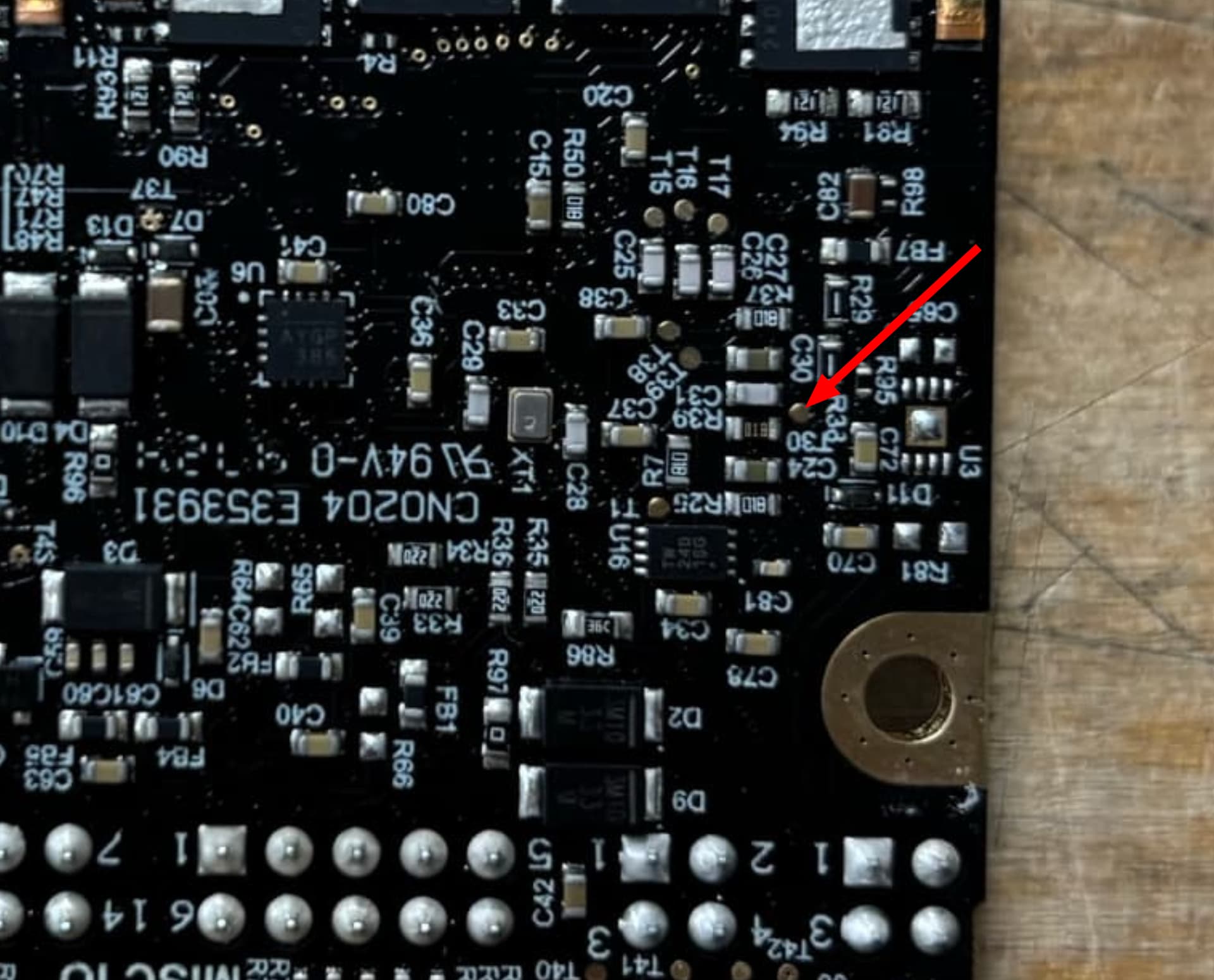
Black lead of the DMM goes to DC-, red lead goes to T30 here:
Could you let me know the voltage? It’ll likely be either about 0.15V, 0.72V, or 0V – each points to a different culprit for this issue.
I performed the test with the 24 V supply connected to DC+ and USB-C connected. With the black DMM probe on DC− and the red probe on T30, I measured approximately 0.79 V.
Thanks again for your help!
Hi! I just wanted to follow up on this thread, as I haven’t heard back since providing the T30 measurement.
Have you had a chance to look at this result? I’d appreciate any advice on what it indicates and what I should check next to diagnose or repair the ODrive Pro.
Thanks again for your time and support!
0.79V is the “divider’s fine” answer. With 24V on the bus, a the sense divider puts about 0.72V on T30, and T30 is wired straight into the processor’s ADC input – so this is a problem with the ADC.
Let’s get this unit swapped out – could you shoot me an email with your original order number and best shipping address?
Out of curiosity, how is the ESP32 wired to the Pro – only the isolated UART pins, or anything on the non-isolated side (shared supply/ground, encoder header)?