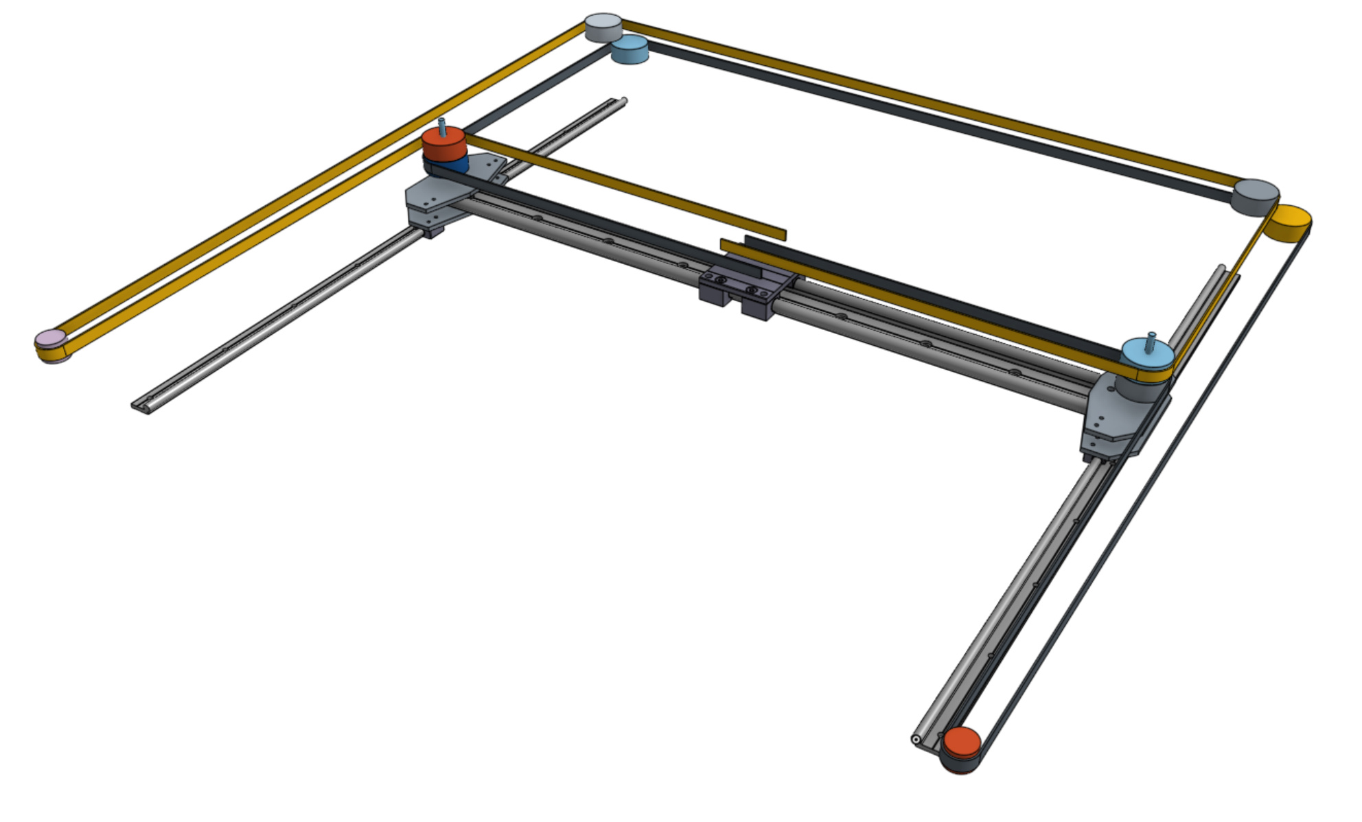
Hi, I just want to share a work in progress: I’m making a 1m x 1m CoreXY machine for demoing ODrive. The design requirements are that it should be able to take the full power of some large size ODrive motors, and have enough stiffness to show off the control accuracy with a pen on paper.
I am using the Igus Drylin-W rails, and I am looking to use some 15mm wide 5mm pitch GT2 or GT3 belts.
Right now I’m trying to figure out how to make the two idler pulley shafts that are riding on the Y carriages anchored stiffly enough to not deflect by more than 0.5mm under 300N belt force.
If you want to have a look around, here is the live document I’m working in. So beware that it have me breaking it and editing it live: OnShape link.
but to solve the deflection, put a cap over the bolt that attaches solidly on both sides. you can even have a cap that anchors on all four sides (leaving slots for the chain to go through to get to the idler)
OK cool, thx for your input! How would you design the part that anchors the cap down to the bottom, onto the plate?
I don’t know about chains at these speeds: the belts will hopefully reach 15 m/s speed.
Yeah the center-carriage belt anchoring needs to take the max force of the belts pulling against each other. Yeah the forces on the bearings is just the belt tension plus the force to accelerate the moving masses.
I would just take the model that you have, add some buffer space around the belts and then model it as a solid part. If you are willing to give me edit access, I can set it up (and show you if you are online at the same time)
I’m pretty sure that the reaction forces at the idlers should be equal and opposite. You could run a rigid link on the unsupported side of the shafts that ties them together which should meet your deflection requirements. Let me know if this makes sense. I’m happy to model it in the Onshape file if it doesn’t!
I thought there was chat in onshape, were you able to follow what I did?
I extruded a thick shape, then I edited in context to be able to define clearances from other components (3mm on the outside, 4mm on the inside) and then extruded that part as a ‘remove’ from the big chunk.
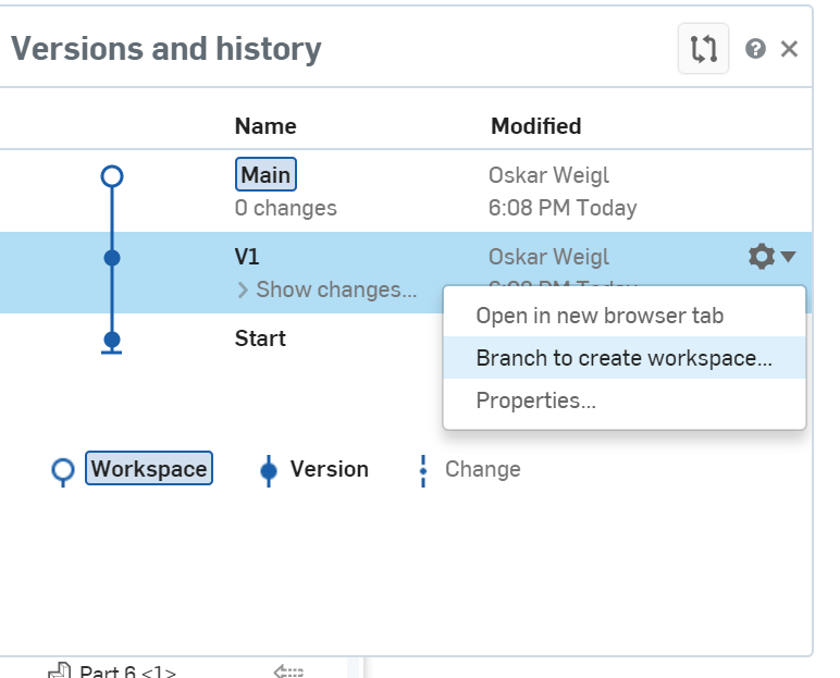
I missed the ‘fork first’, but it’s easy enough to fork at v1 if you want to throw this away and do it differently.
This is chunky, I didn’t bother trying to streamline the outside.
I see! You seem to have alot of other exciting stuff going on though
Im thinking it would be possible to use V-slot aluminium extrusions or something similar. The IGUS Drylin rails is probably more expensive, although I dont know the price exactly.
Maybe a V-slot square, with a crossbar attached to the frame via a V-slot gantry plate in each end. Another gantry plate on the crossbar for the X-axis.
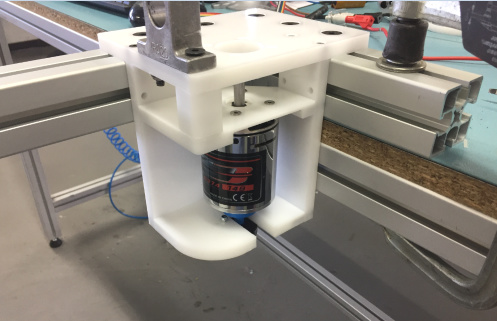
The motors can be mounted outside the square via 3D-printed parts connected via t-nuts to one of the aluminium profiles. The same goes for the idler pulleys in the corners. The other idlers pulleys can probably be mounted on the gantry plates. It feels like it would be a good idea to print these mounts completely solid in polycarbonate or nylon.
I´ll try to make an assembly of this in Inventor
What do you think of this?
Maybe 20x20 extrusions will not be enough to get sufficient stability with a 1x1m square. There are 40x40mm V-slot rails available that could be more suitable. Or the 20x80 as dlang suggested.
It would be nice to keep it to belts i think. Maybe fiber reinforced belts would be enough?
I am not familiar with such high loads as this, so if anyone see obvious weaknesses please let me know!
Hi everyone, I saw this cross-referenced in another post where some good advice came in from @Larock1234 about the drylin bearings. @madcowswe have you already bought your parts and are you open to a change in kinematics?
I have a CoreXY 3D printer that I designed and built myself. It’s not the most amazing thing but I like it and I think the process of making it has given me some insight into basic machine design of this nature. Before I hopped over to this thread I looked up some kinematic designs/strategies because @pi3d was referencing an ultimaker style printer in a youtube video. I wondered if that was going to be optimal in terms of dynamic mass and had a look at e.g. 5mm linear rail and carbon fibre square tube (I have no idea what the budget is here!). Seems like you can go cheaper and lighter with different kinematic strategies than the ultimaker but corexy requires a stiff frame to deal with racking forces, even though it’s better than H -bot.
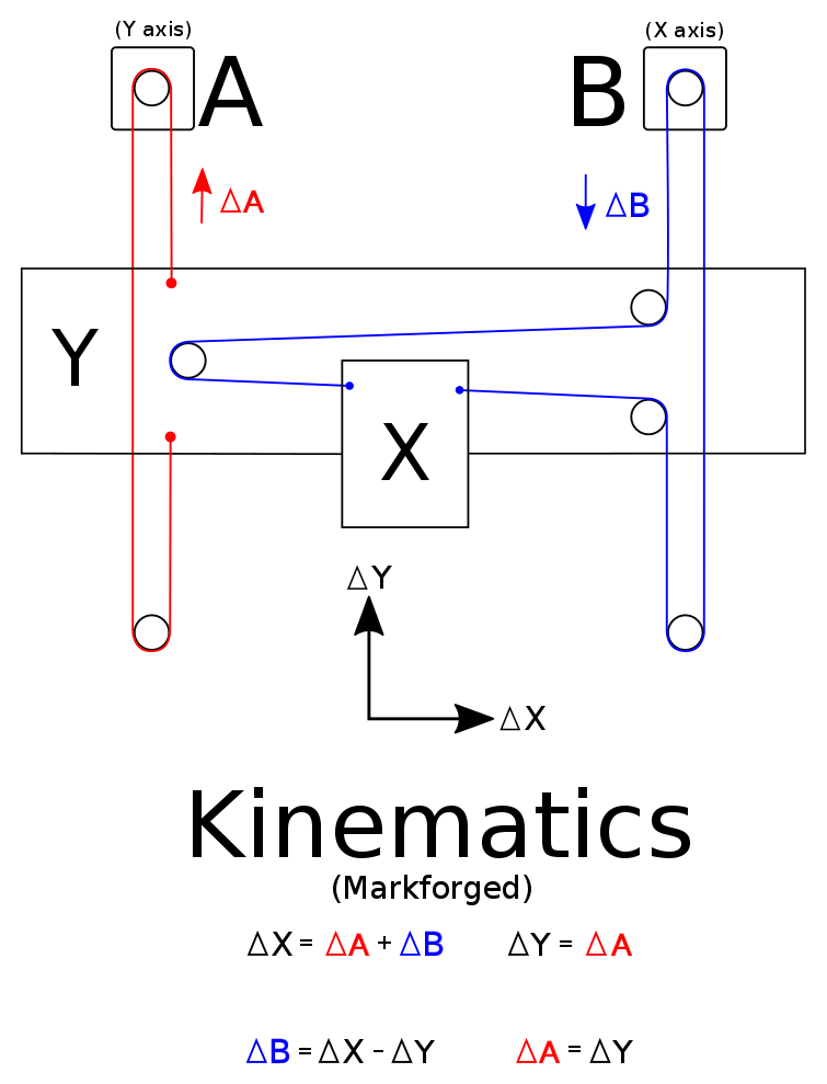
Then I came across this sadly sparse project on Hackaday.io which references the Markforged kinematics and would potentially allow the belts to operate on the same plane, reducing or eliminating racking forces and hence the stiffness requirement on the frame. It would also appear to allow you more leeway in tensioning the belts independently.
If the tool head is still intended to be a pen and z-axis lift (micro servo or pneumatic/solenoid for speed?), a single, thin linear rail could work with carbon fibre strip to resist lateral forces could work. Or a square section and perhaps a pair of thin rails if you think there’s going to be a significant toolhead-generated moment around the gantry under acceleration.
i’m working a 0.8m x 1.2 m corexy myself those days. using odrive to power it. I was inspired with your pick&place demo that you showed during the fair last year. I have experience in building several corexy design solution in production already (albiet on a smaller version like 30cm x 30 cm)
my goal is to prove that i can use the odrive concept for serious production.
I’m confident that i can do it alone. But it would be so much more fun to do it open source / open hardware.
I would even pay for your bill of material directly sent over to you in California if you agree that we join forces on an open hardware approach.
Are u interested?
My only concern is that I mostly work with freecad and feel a bit uncomfortable with onshape. (i guess i can learn :p)
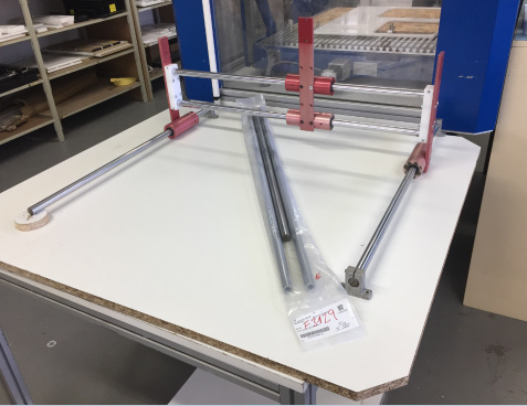
great. i can accomodate to igus rails or we keep the design I offer (i used what i had available nearby + i want to do some heavy duty work to either prove the thing works or actually break it => hince the 20mm hardened steel shafts.)
as a side note, i can see on your inshape screenshot that you intend to use non aligned pulleys, and i beleive it is not compact/simple enough. i’ll offer you what i beleive is a better belt design.
i’ll send u a pm so that we organize the next steps.
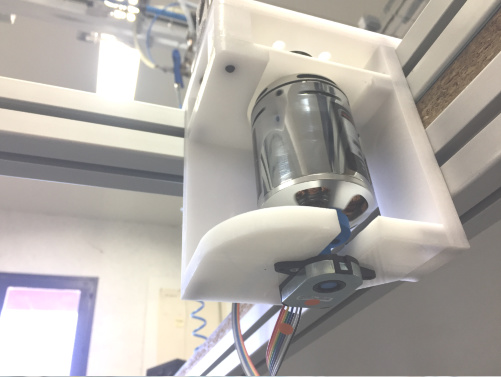
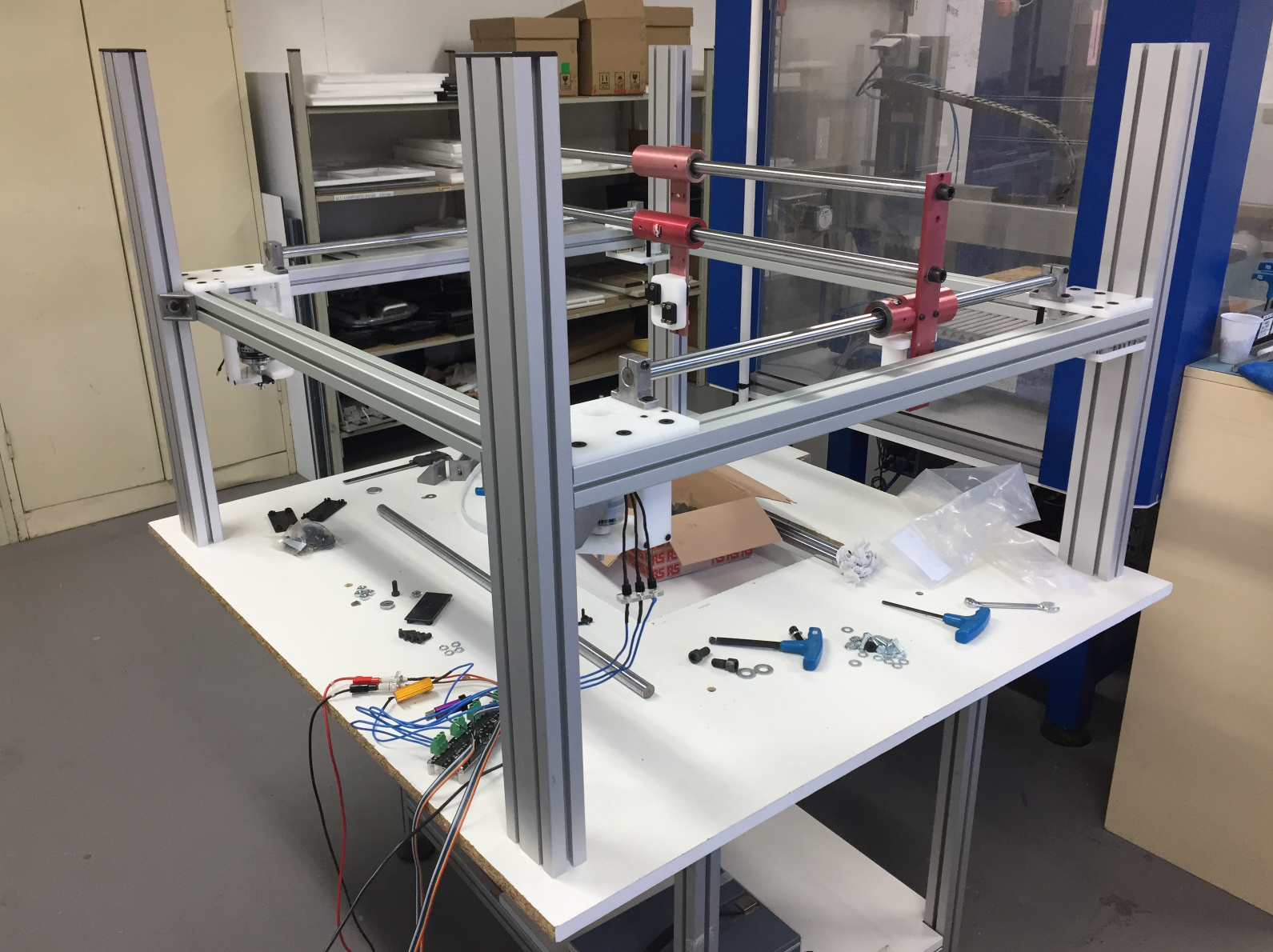
as per agreed, we’ll keep separate projects. just to share some progress. but i’m always on the go. can’t decently work on that one
the beast is massive. I never used so big screws. I used 15mm belts but i couldn’t find GT2 5mm above 2m lengths on misumi so I had to switch to another type of tooth profile that resulted in pullies that i couldn’t make myself (@madcowswe, where did you source your 15mm width GT2_5mm belt? Ideally I’d like a 10m spool so that I forget about this issue altogether.)
Can’t wait to finish mounting everything to see what those motors can deliver with my 24V odrive.

 => hince the 20mm hardened steel shafts.)