Hi All,
I’m building a Direct Drive sim racing steering wheel based on the hoverboard tutorial and the EMC Arduino project. I want to isolate the ODrive from the Arduino as whilst everything works well in general I’m getting glitches when the ODrive is powered.
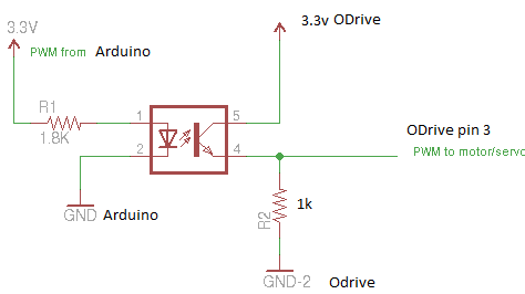
That being the case I want to try and opto-isolate the Arduino to Odrive connection.
The Arduino firmware outputs Servo PWM using the Servo library.
I’m using a PC817C optocoupler, the Arduino output is 3.3v and I’m using a 1k8 current limiting resistor on the PC817C input side pin 1. As per below
On the output side of the optocoupler I’m connection the optocoupler (Picture) pin 4 to the ODrive IO pin 3 and I’m using a 1k pull down resistor to ODrive ground. Pin 5 (Picture) is connected to ODrive 3.3V.
When powered the ODrive is continuously running in 1 direction, so I’m guessing that either the pwm pulse length is getting shortened or I’m just not getting a signal and ODrive pin 3 is just fixed at 0v or 3.3v.
Can anyone suggest a good set of values for the resistors to make this work? Or am I way off the mark? Some googling suggests a 10K pull down would be more appropriate, but I’d rather not just randomly try different values, especially considering I’d rather not damage my ODrive and I dont know what signal conditioning is inside the it to start with. I know just enough about electronics to be dangerous lol, so I thought it better to ask.
I’d also like to use the same rotary encoder for both the Arduino and the ODrive, currently the ODrive uses the hoverboard motors hall effect sensor wiring, and the Arduino uses a 5v rotary encoder. Again I’d like to separate the two devices with an optocoupler, will the same circuit work for the A B Z Encoder inputs for the ODrive?
Any constructive feedback would be most appreciated.
Some nice wiring there, I must say
I like your brake resistor on standoffs with the crimped connectors
Your circuit should work… Personally I would have inverted it and made the optocoupler as a pull-down across the resistor instead of in series, but there’s no reason why your arrangement shouldn’t work… Do you have a scope to check that it is working?
If the ODrive is running in one direction only, then most likely you have configured the PWM endpoint wrong. If your maximum is 10, then your minimum should be -10, not 0.
However, it might be simpler (and more powerful) to use a UART connection from the Arduino instead… Have you tried that?
Well, that depends on the opto. As drawn, ODrive pin 3 should be on the opto Pin 5, with ground on opto pin 4 and a pull-up from odrive to 3.3v. This results in an inversion, though, which is annoying and probably why OP didn’t do that in the first place.
Several people have made nice isolator boards with the ISO776x series isolators, see OTS Opto-Isolator for UART Ground Loop for example (or search on the forum for more). I recommend grabbing one of those designs instead, as the ISO will drive things properly instead of using resistors.
Hmm. This opto is a 2-terminal device with no ground reference, so why should it care if it is on the high-side or the low-side?
Yes, a normal NPN transistor needs to be in an inverting configuration, but a phototransistor should just pass current, no?
There is no base current that needs to flow to ground - the “base current” is provided the photoelectric effect.
The convention is to invert it like a normal transistor though (as I said) but I think it will still work this way. You’re right that the edges will probably be too slow though - especially for encoder signals.
@cncmodeller Everything Wetmelon said is good advice. If you use a basic optoisolator and a resistor, the output edges will be slow - that will put a limit on the Arduino’s PWM frequency, and also on the motor speed if you want to use it for encoder signals.
Use a PCB with an isolator designed for fast digital signals - these chips have built-in opamp schmitt-trigger circuits, which boost the frequency response and give a proper digital totem-pole output.
Or use UART, or CAN instead
Also you shouldn’t “need” to isolate encoder signals. If you find that you do, there’s probably something else wrong, like excessive noise on your motor wires. A ferrite choke can help that.
I’m using RC servo pwm as the firmware for the Arduino isn’t open source and servo pwm is the only compatible interface that I believe I can use.
I may create an interface board to translate servo pwm to CAN but I’ve never used it before. I have bought a can interface board so it’s something that I will get to eventually.
I just wanted to isolate things as much as possible to future proof the project in case I want to make several for friends in the future.
I don’t have a scope but I’m thinking that it’s probably a response issue. I’m going to test the board between an rc servo tester and a servo to see if I can get it working with less risk of damage to expensive components.
As far as I understand this device can be used non inverted as per the diagram so I agree with @Wetmelon on that front.
I’ll look at a digital specific isolator boards and the ground loop post.
Many thanks guys, your comments have been really useful. I’ll let you know how I get on