Just recently read the write up on ground loops and we have plenty of them
Specifically, we have several arduinos connected to odrives uart pins tx/rx/gnd. Assuming the ground is necessary we will need to decouple these lines.
Is there a way to turn down the UART baud rate on the ODrive to 9600? I have been looking through the firmware and I can’t find an easy way to do that.
Are there any recommended GPIO/UART isolators to use available on breakout boards?
We’re using Sparkfun’s differential i2C breakouts to create a CAN alternative for ease of use and are planning to roll that into our production model. CAN just wasn’t ready for us on ODrive based on our timeline and the cost of integration was too high for our situation.
If anyone has recommendations on UART decoupling we’d greatly appreciate it.
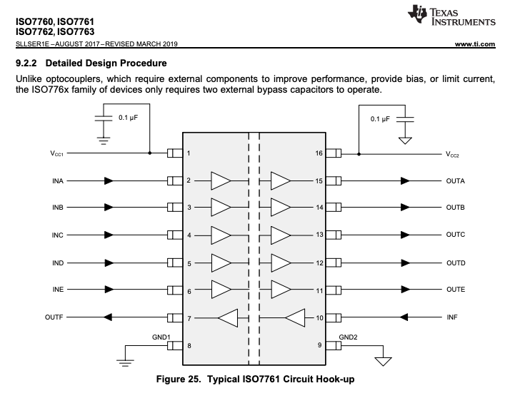
For anyone else following along, looking at the ODrive docs recommendation of the TI ISO7762F it does look very strait-forward. They have a dev board for $50 here. Way too expensive for production but worth a look. We might dive deeper into this and make a quick breakout board, will post links to eagle files here if that’s the direction we go. Would love to see this chip integrated into the ODrive for communications isolation it looks great for $3.80 in single quantities.
We are also in the process of designing a “Hat” for the ODrive that isolates the GPIO and provides for differential SPI encoder connections and differential incremental encoders
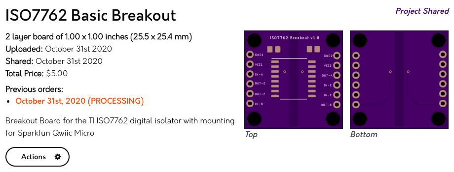
Hey Ya’ll, just finished this breakout design and posted on OSHPark. I designed this for our application which uses several Sparkfun Qwiic Micros. Mounting and headers should align so that you can solder header pins between the Micro and this board and have full isolation on TX/RX and D0/D8. This is a quick first pass so feedback welcome.
I’m surprised to hear that. It was quite the opposite experience for me. “Differential I2C” was a nasty hack that some predecessor at my work used, with all kinds of spurious faults that went away when you tried to diagnose them but cost us hours of lost data when in the field. Whereas CAN ‘just works’. (provided you set it up right in the first place, but both ODrive and Linux do that part for you: you just give them a ‘baud rate’ like on a serial port)
The “CANSimple” protocol of ODrive really could not be simpler. It is much easier than I2C, that’s for sure.
“Cost of integration” is a board with two chips on. £30-£50 to buy someone else’s board, or £5 if you can design your own. But you only need that once, for all ODrive axes.
@towen thanks for your feedback. Like I said, CAN wasn’t the right solution for us and I can certainly see how it’s the right solution for other folks. Just trying to add new flavors to the mix here.
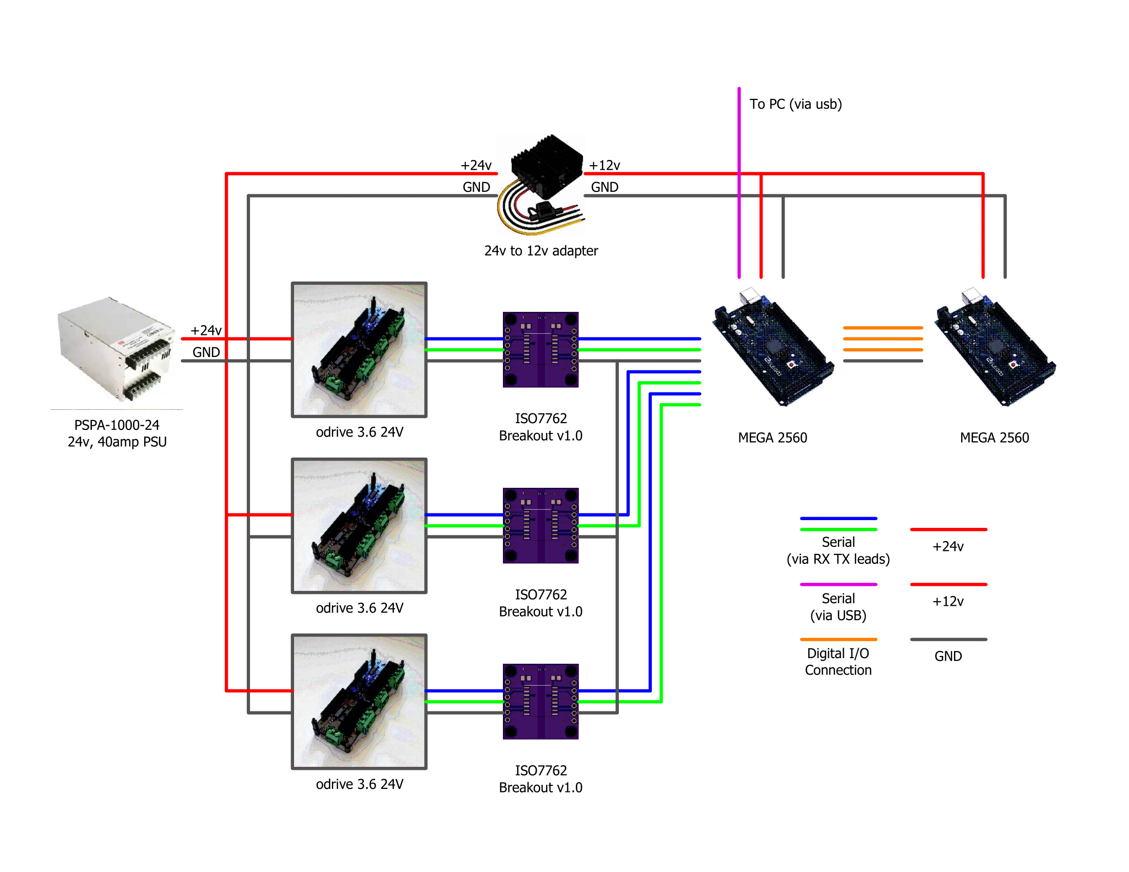
Hi @Alexander_Jones, I was also looking into making something that could protect ground loops over the last couple of days, as I’m ready to plug in 2 x ODrives to Arduino Mega Serial 1 & 2.
I was of the opinion that Opto-Isolation were slow and relatively expensive, although now being introduced to the ISO7762F chip at 100Mbps by yourself and @madcowswe , and especially seeing your breakout board I’ve decided to give them a go. Also, the fact that it will isolate CAN and SPI is very promising.
Thank you for sharing this.
I’ve ordered 9 of these (as they come in 3’s per order for $5 (very good value)) , where I chose the free postage of 21 days to the UK (could have got it faster, but not in a rush for the additional cost).
I’ve ordered the SMD Parts listed above also, so will let you know how I get on. I’ll still be trying This idea also just in the interim, but for peace of mind, I will settle on the ISO7762F and your breakout all being good.
Hi @Alexander_Jones, will let you know, everything has arrived, although running the mill on a Christmas project at the mo, will fit one of these to it once complete and let you know
As I’ve had some success controlling one odrive via UART I will likely stick to using this for the time being. In the near future, I would like to give linking everything up via CAN a go, however being a complete novice this seems a bit far fetched for me right now…
yes, just be aware if you plug in USB to both the Arduino and the ODrive at the same time, you’ll make a ground loop through the USB GND. You can use a USB isolator (available at ODrive shop) to fix this.
Although, I have looked and the ISO7763 chips seem to be out of stock pretty much everywhere until next year I will spend some time looking for an alternative tomorrow, but if you know of a suitable alternative, that would be very helpful.
Hi,
I was able to order ISO7761, maybe they are available in your country too. As I understand it, it should work with UART, because UART only requires one wire in each direction.
Isn’t there also a ground loop via the PSU, depending on whether GND at the PSU is referenced to mains earth?
Either the main PSU or (ideally) the 24V to 12V adapter should be isolated.
Unfortunately, none of my go-to suppliers seem to have any of these either here in the UK
Forgive my ignorance, but wouldn’t this be alleviated by using the usb isolator, or am I misunderstanding? Fortunately, the voltage adapter I’m planning on using - Mean Well RSD-60 60W (not shown in original diagram), provides isolation, so I think I’m good? Nevertheless, if you could explain why it could cause a loop, I would appreciate the opportunity to learn!
The more I look into it, the more it makes sense to use a CAN connection. I think I will bite the bullet now and proceed using the MCP2515 module. Here is my proposed layout:


 I will spend some time looking for an alternative tomorrow, but if you know of a suitable alternative, that would be very helpful.
