I am trying to use the ODrive with a hub motor and AS5304 magnetic encoder with a ring magnet with 44 poles => CPR = 22 * 40 * 4
When it is doing the calibration it just moves a little and then it stops
if I run “g 1 3” I get 3 which I found it to mean ERROR_PHASE_RESISTANCE_OUT_OF_RANGE
I did read the phase resistance value (g 0 12) and it is 0.0
I also checked the AB signals from AS5304 with an oscilloscope and they look ok (I was mainly worried it’s not reading the values properly but it’s not the case)
I think your hub motor may have a larger resistance than 1 ohm. I pushed a change to master just now that allows you to see the measured resistance even though it thinks it’s too large (that is, despite giving ERROR_PHASE_RESISTANCE_OUT_OF_RANGE).
Can you pull master and then flash and check what resistance the ODrive thinks your motor is?
If your motor is indeed more than 1 ohm, we should just reconfigure some parameters and you should be ok. I’ll let you know what to change once we know what the resistance was.
Thanks for the quick reply!
I updated and these are the results:
g 1 3 = 3 (error code motor 0)
g 2 3 = 0 (calibration_ok motor 0)
g 0 12 = 0.100000 (phase resistance motor 0)
I used my multimeter to measure it and while measuring resistance between the 3 leads I get values between 0.8 and 2.0 ohms so I don’t think it’s very trustworthy
I then looked at the code and found
if (fabs(test_voltage) == fabs(max_voltage) || R < 0.01f || R > 1.0f) {
    motor->error = ERROR_PHASE_RESISTANCE_OUT_OF_RANGE;
    return false;
}
the only voltage exposed is the bus voltage so I ran “g 0 0” = 24.459961 but it looks not related to this method at all
So the ODrive is designed mostly around hobby motors, which are lower resistance.
You can still use ODrive, but you should be prepared that the current (and hence torque output) will be quite noisy. You can make this better by changing the shunt resistor values on the board (by desoldering the current ones and soldering on replacement ones).
Before doing that, however, you can try to see if it’s okay anyway. You must change some defaults to be able to measure the resistance:
In low_level.c,
change .calibration_current to 4.0f
on the line that says if (!measure_phase_resistance(motor, motor->calibration_current, 1.0f)), change the 1.0f to 10.0f
on the line that says if (fabs(test_voltage) == fabs(max_voltage) || R < 0.01f || R > 1.0f) change the R > 1.0f part to R > 2.4f
change static const float kI = 10.0f; //[(V/s)/A] to 50.0f
Let me know if you have any problems with this and I can try to explain more.
EDIT: Step 2 is now depricated, instead try increasing .resistance_calib_max_voltage.
I made the changes and now calibration works
g 0 12 = 0.338152
As the measured resistance is not above 1ohm I think I should mention that this is a 80kv motor (500W I think) that has very high cogging torque and the calibration and all movements are in steps, not smooth at all
Motor has 8 pole pairs and 12 stator slots
When in position control it basically oscillates between between the 2 cogging positions on both sides of the required position
It is my understanding that cogging torque is directly proportional to motor torque in slotted motors which is something I need, high torque and low RPM so can’t really get around that
I read the post about cogging torque compensation and I’m going to try it and see how it goes
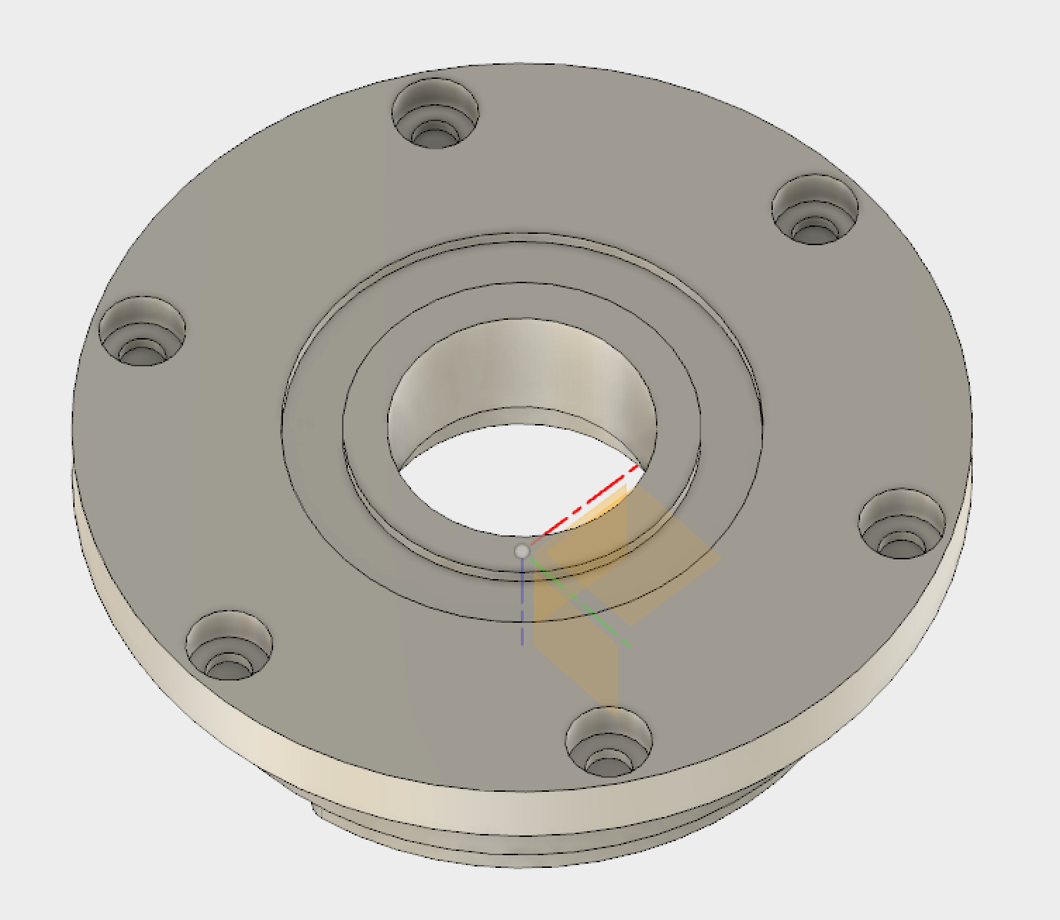
I replaced the motor cap with a custom machined one (my wheels are wider than the motor so I had to make it longer anyway) and I added an extrusion on the motor cap to fit the magnetic ring
Hi guys,
I have more or less the same problem and I need your help. I get Error #3 - ERROR_PHASE_RESISTANCE_OUT_OF_RANGE after startup.
I use the latest Firmware and did all four steps mentioned above. They didn’t help.
The Motor I am using has the following parameters:
Values at nominal voltage
Nominal voltage 12 V
No load speed 4360 rpm
No load current 163 mA
Nominal speed 2910 rpm
Nominal torque (max. continuous torque) 54.9 mNm
Nominal current (max. continuous current) 2.02 A
Stall torque 247 mNm
Stall current 9.69 A
Max. efficiency 76 %
Bearing type ball bearings
Max. speed 10000 rpm
Axial play 0 - 0.14 mm
Max. axial load (dynamic) 4.8 N
Max. force for press fits (static) 53 N
(static, shaft supported) 1000 N
Max. radial load 18 N, 5 mm from flange
Other specifications
Number of pole pairs 8
Number of phases 3
Product
Weight 75 g
Could you please give me a hint about what I could try to do or how I should debug this kind of problem?
My mistake was to rely on changes in low_level.c. But they are overwritten after flashing. I used explore_odrive.py and did the changes there (don’t forget to save the config with my_odrive.save_configuration() )
After changing the parameters, I got another error #6 - ERROR_PHASE_INDUCTANCE_OUT_OF_RANGE. I read this post and set the Parameters lower: motor0.resistance_calib_max_voltage = 6.0f and motor0.calibration_current = 3.0f since my power supply is limited to 3.2A
Now I had no errors, calibration worked but I had vibration and >1A in “standstill”, like in this post. Setting vel_gaim five times lower to my_odrive.motor0.config.vel_gain = 0.0001 helped.
That was it!
@madcowswe, would you please explain what’s the logic set the kI value to 10? Currently I’m trying to understand the logic behind the measure_phase_resistance and measure_phase_inductance in motor.cpp.
I found the unit of kI is [(V/s)/A], but difficult to understand why set it to 10. Appreciate if you can give some explanation.