Sensorless pole slipping on ramp-up under propeller load — torque_constant sensitivity (T500, ODrive Pro 0.6.12)

axis0.config.motor.motor_type                  MOTOR_TYPE_HIGH_CURRENT
axis0.config.motor.pole_pairs                  7
axis0.config.motor.torque_constant             0.04544
axis0.config.motor.phase_resistance            0.0756
axis0.config.motor.phase_inductance            4.05e-05
axis0.config.motor.current_soft_max            95.0
axis0.config.motor.current_hard_max            100.0
axis0.config.motor.sensorless_observer_gain    500.0
axis0.config.motor.sensorless_pll_bandwidth    500.0
axis0.config.motor.bEMF_FF_enable              True
axis0.config.motor.wL_FF_enable                True
axis0.config.sensorless_ramp.current           20.0
axis0.config.sensorless_ramp.vel               14.0
axis0.config.sensorless_ramp.accel             31.8
axis0.config.sensorless_ramp.finish_on_vel     True
axis0.config.sensorless_pm_flux_linkage        0.0
axis0.controller.config.control_mode           CONTROL_MODE_VELOCITY_CONTROL
axis0.controller.config.input_mode             INPUT_MODE_VEL_RAMP
axis0.controller.config.vel_ramp_rate          20.0
axis0.controller.config.vel_gain               0.5
axis0.controller.config.vel_integrator_gain    0.333333
axis0.controller.config.vel_integrator_limit   3.5
axis0.controller.config.vel_limit              50.0
config.dc_bus_overvoltage_trip_level           56.0
config.dc_max_positive_current                 50.0

ODrive Pro, firmware 0.6.12-1. Blue Robotics T500 thruster, 7 pole pairs, running
sensorless at 48 V with a propeller fitted in water. Velocity control, VEL_RAMP.

Commanding 0 → 70 rad/s, the motor sometimes fails to hold commutation during the
ramp: an audible repetitive knock, phase current climbs to the soft-max clamp, and
the velocity estimate wanders well away from the setpoint before it either recovers
or settles low. It is intermittent and load-dependent — the same command on the same
drive with no water load runs clean.

Chasing it, we found the behaviour is very sensitive to torque_constant. Two
back-to-back runs on the same drive, identical command and identical ramp settings,
changing only that one value:

                            Kt = 0.021205      Kt = 0.04544
  time to 90% of 70 rad/s        2.31 s            1.56 s
  slip events                    5                 0
  steady-state spread            47.36 rad/s       3.18 rad/s
  steady-state stdev             9.4 %             1.2 %
  peak phase current             95.3 A            34.8 A

0.021205 is what the published 390 Kv rating gives via 8.27/Kv. 0.04544 is what we
measured on the bench for the same motor. With the lower value the loop asks for
roughly twice the current for the same torque, pins against the 95 A soft-max, and
has no authority left; because sensorless_pm_flux_linkage is 0.0 and therefore
derived as (2/3)·Kt/pole_pairs, the same number also halves the estimator’s back-EMF
model. The result is 95 A of phase current against no more than 23.9 A of bus
current — a lot of current producing very little torque.

Running on the measured 0.04544 removes the slipping on ramp-up entirely in this
configuration, so we are not blocked. What we would like to understand is the
residual case: under steady load we still occasionally see commutation lost with a
velocity estimate that stays plausible rather than collapsing, so the spinout
detection does not fire and nothing is reported — the drive keeps commanding current
into a rotor it is no longer tracking, and the first visible symptom is thermal.

Could you please help us identify the possible root cause of this issue?
Hi there,

Apologies for the slow reply on your other thread, I’ll address the issues overall here.

A few notes:

  • Yes, sensorless is quite sensitive to accurate torque_constant measurements, so is the bEMF_FF_enable term.
  • T500 thruster shows as KV = 202 RPM/V on the product page. So torque constant should theoretically be about 0.0409. Where are you getting the 390 Kv number from?
  • If you measured 0.04544 Nm/A on the bench (I assume using an oscilloscope method as shown here), that’s a better value to use
  • I would avoid changing sensorless_pm_flux_linkage. The automatically calculated value is best.
  • Typically minimum sensorless speed is that corresponding to about 1-2V of back-EMF. For a 202 RPM/V motor, this would be around 202-404 RPM. Your sensorless_ramp.vel handoff speed is 14 Hz / 7 pole pairs = 2 rev/s = 120 RPM. So I’d definitely recommend increasing sensorless_ramp.vel to about 202/60*7 = 23.5 minimum, ideally around 28-35, and not commanding speeds under about 3.5-4 rev/s (about 210-240 RPM). Note though that load raises the minimum speed floor; so I’d recommend keeping the velocity around 300 RPM minimum if possible.

“The result is 95 A of phase current against no more than 23.9 A of bus
current — a lot of current producing very little torque”

note that bus current and motor current are different – motor current will almost always be larger than bus current (especially at low speeds); you cannot tell the actual torque-producing motor current without a reference position. So while it is likely true you’re losing the sensorless observer tracking, this discrepancy isn’t necessarily related.

under steady load we still occasionally see commutation lost with a
velocity estimate that stays plausible rather than collapsing

What velocities?

From your other post:

Our current suspicion is that winding self-heating at 40-80 A makes the stored phase_resistance stale within seconds, progressively degrading sensorless alignment under load.

Yes, a raising phase_resistance does impact the sensorless observer. Though in your other post, you were running the incorrect torque constant, so this will have a very outsized effect. Also, you observed a warm phase_resistance lower than the original value; copper rises in resistance with temperature, so this is likely just measurement noise.

Your calibration_current is only 10A; I would recommend raising this to about 40A to reduce measurement error. You will likely have to increase resistance_calib_max_voltage to around 6-8V as well.

Since bEMF_FF and wL_FF are both based on the measured velocity, which may be unreliable here, I would recommend keeping those off.

I’d also recommend keeping sensorless_observer_gain around 200.

Since you’re streaming Iq and bus current anyway, the robust check for motor protection is host-side: Iq well above what that velocity should need for ~1 s → IDLE, wait for spin-down, relaunch.

Thank you — that fixed the ramp-up problem completely. Applied all of it:

axis0.config.sensorless_ramp.vel              14   -> 35
axis0.config.motor.sensorless_observer_gain   500  -> 200
axis0.config.motor.calibration_current        10   -> 40
axis0.config.motor.resistance_calib_max_voltage 2  -> 7
axis0.config.motor.bEMF_FF_enable             true -> false
axis0.config.motor.wL_FF_enable               true -> false
axis0.config.motor.sensorless_pm_flux_linkage 0.0 (left automatic, as advised)

Startup now succeeds every time and there are no slip events on the ramp.

We then swept velocity under the propeller, re-arming from IDLE at every level
rather than stepping a live staircase, 30-60 s per level, 48 V bus, 7 pole pairs,
torque_constant 0.04544 measured on the bench:

cmd rad/s   measured        iq_A    bus_W    result
   40       40.0 +-1.1      11.9      45     stable
   50       50.0 +-1.2      16.4      76     stable
   60       60.0 +-1.3      22.1     131     stable
   70       70.0 +-1.2      32.8     232     stable
   80       79.9 +-1.2      40.7     383     stable
   90       see below       52.2     626     loses lock after ~22 s
  100       see below       81.1    1286     loses lock after ~4 s

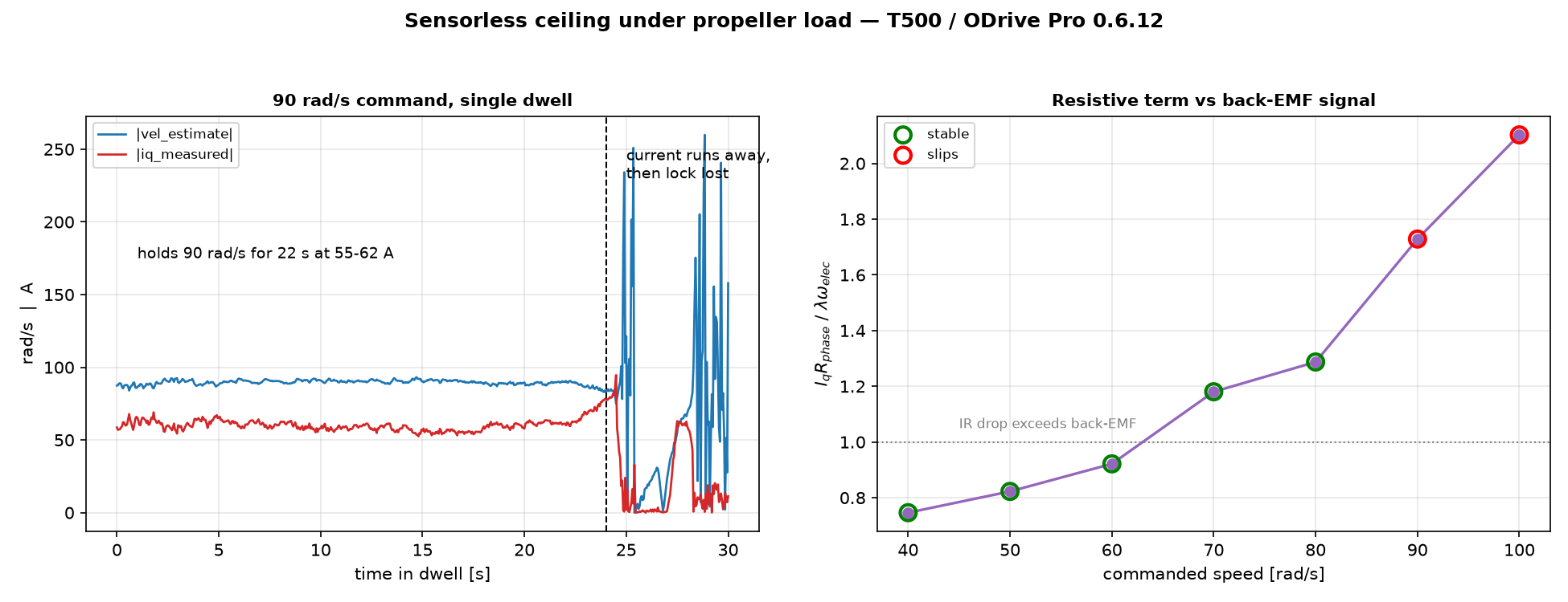
Graph 1 → the 90 rad/s dwell: 22 s holding the setpoint at 55-62 A, then iq runs
away to 78 A and commutation is lost. Graph 2 → the resistive term divided by the
back-EMF term at each level, green stable, red slipping.

Below 80 rad/s tracking is exact and steady. Above it the axis holds the setpoint
correctly for a while and then loses lock, and the time it survives shrinks as
speed rises — 22 s at 90 rad/s, 4 s at 100. After the loss, vel_estimate reports
speeds up to 157 rad/s at near-zero current, so the estimate stays plausible while
the shaft is not turning at anything like that.

What we think is happening: a propeller is a square-law load, so current grows as
omega^2 while the back-EMF the observer works from grows only as omega. The
resistive term therefore overtakes the back-EMF term linearly with speed. Using
the automatic flux linkage (2/3 * 0.04544 / 7 = 0.004328 Wb) and the calibrated
phase resistance of 0.0759 ohm:

cmd rad/s   Iq*R      lambda*w_elec   ratio    result
   40       0.90 V       1.21 V       0.75     stable
   60       1.67 V       1.82 V       0.92     stable
   80       3.09 V       2.40 V       1.29     stable
   90       3.96 V       2.41 V       1.64     slips
  100       6.15 V       2.93 V       2.10     slips

(The phase resistance above was calibrated before we raised calibration_current
to 40 A, so it may shift once we recalibrate; it is a common factor across all
the levels, so the ordering is unaffected.)

The boundary falls between 1.29 and 1.64 in every run. That would also explain the
delay before failure: there is no motor thermistor on this unit, phase_resistance
was calibrated cold, and at 50-80 A the windings heat quickly during the dwell, so
the resistance the observer is using drifts further from the true value the longer
it runs — fastest at the highest current, which is the order we see the failures in.

Could you please advise whether this ratio is the right thing to be designing
against, and what the practical ceiling on it is for reliable sensorless operation?

Glad that sorted the ramp, and thanks for the nice dataset.

Could you please advise whether this ratio is the right thing to be designing against, and what the practical ceiling on it is for reliable sensorless operation?

Not quite. The observer subtracts I*R using the configured phase_resistance, so the resistive term itself is fine as long as R is accurate – with a good R, a ratio of 2+ works. What affects things is the error in that subtraction (R drifting with temperature, plus any inverter voltage drop that the observer doesn’t see); the ratio is just how much that error gets amplified. Also, 90 rad/s should be 2.73V of back-EMF, not 2.41 – that point is ~1.45.

For a square-law load that works out to roughly the same tolerable R error at every speed: at sensorless_observer_gain = 200, lock is lost once the true (hot) resistance is ~40-50% above the stored value, i.e. around 100°C of winding rise from wherever you calibrated. So the sweep is really measuring how fast the copper heats (I²R), which is why survival time shrinks with current rather than there being a hard speed boundary.

That’s a lot of heating for 22s though, so worth confirming directly: run MOTOR_CALIBRATION immediately after a 90 rad/s failure and compare to cold. Every 4% on R is about 10°C. If it comes back under +20% or so, this isn’t the mechanism.

Things that can buy you margin:

  • sensorless_observer_gain = 100. Doesn’t change the heating, but the tolerable R error goes to roughly +65%.
  • Calibrate hot (right after a run) at 40A. Erring high on R is safe and erring low is not – the inverter drop looks like an extra ~15-20% of R at 50A, so a slightly high value actually cancels it. You can also just increase the configured phase_resistance by 20-30%. Even better, if you have an LCR meter, it would be good to get a source-of-truth measurement from that, both at cold and at hot.

A few questions:

  • How long between the 90 rad/s failure and the 100 rad/s run? The 4s only fits the picture if the winding was still hot.
  • What did the 40A calibration give vs 0.0759?