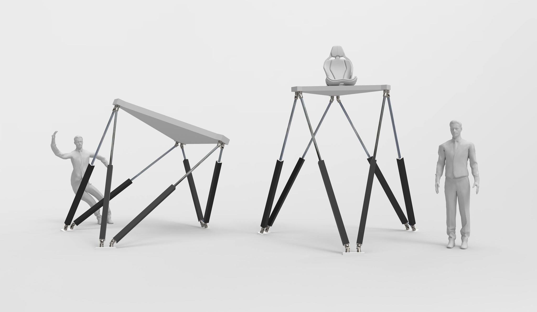
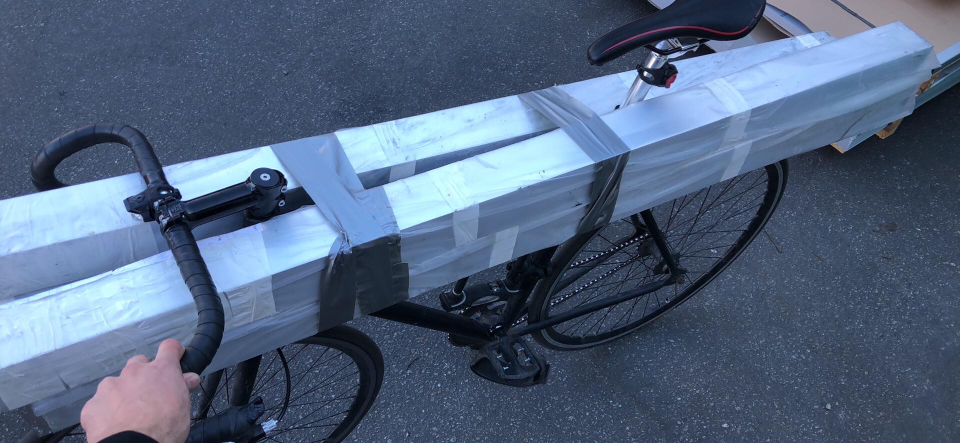
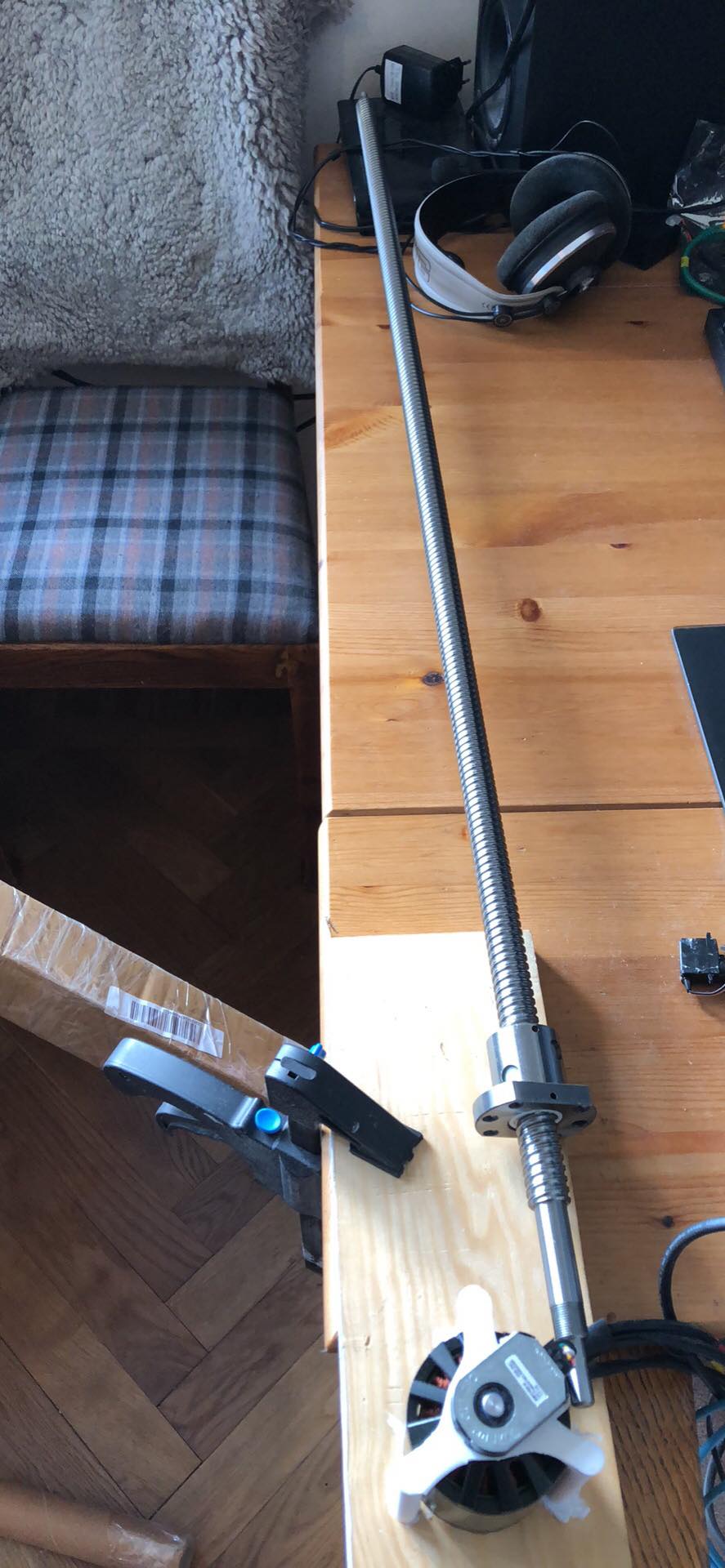
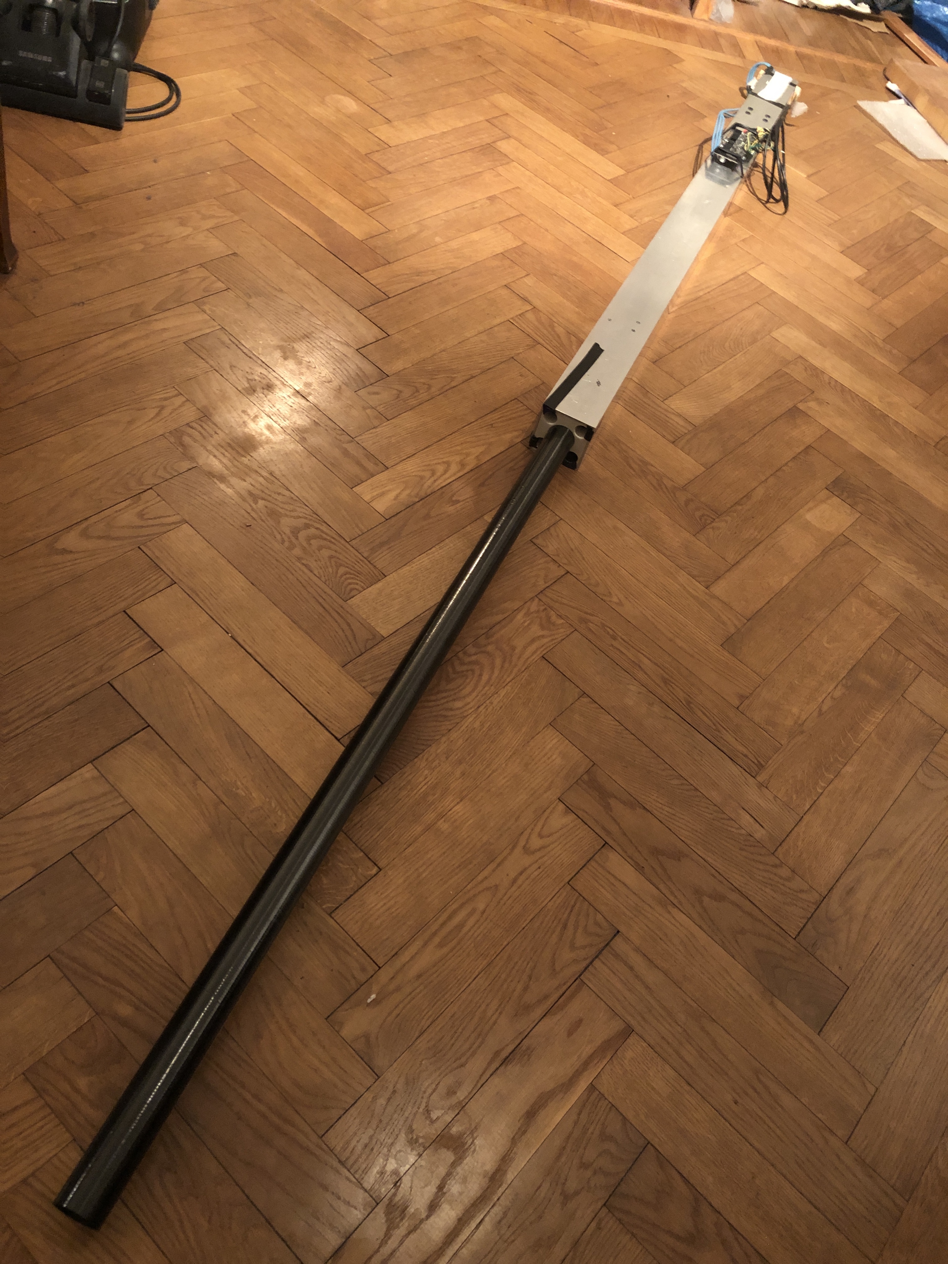
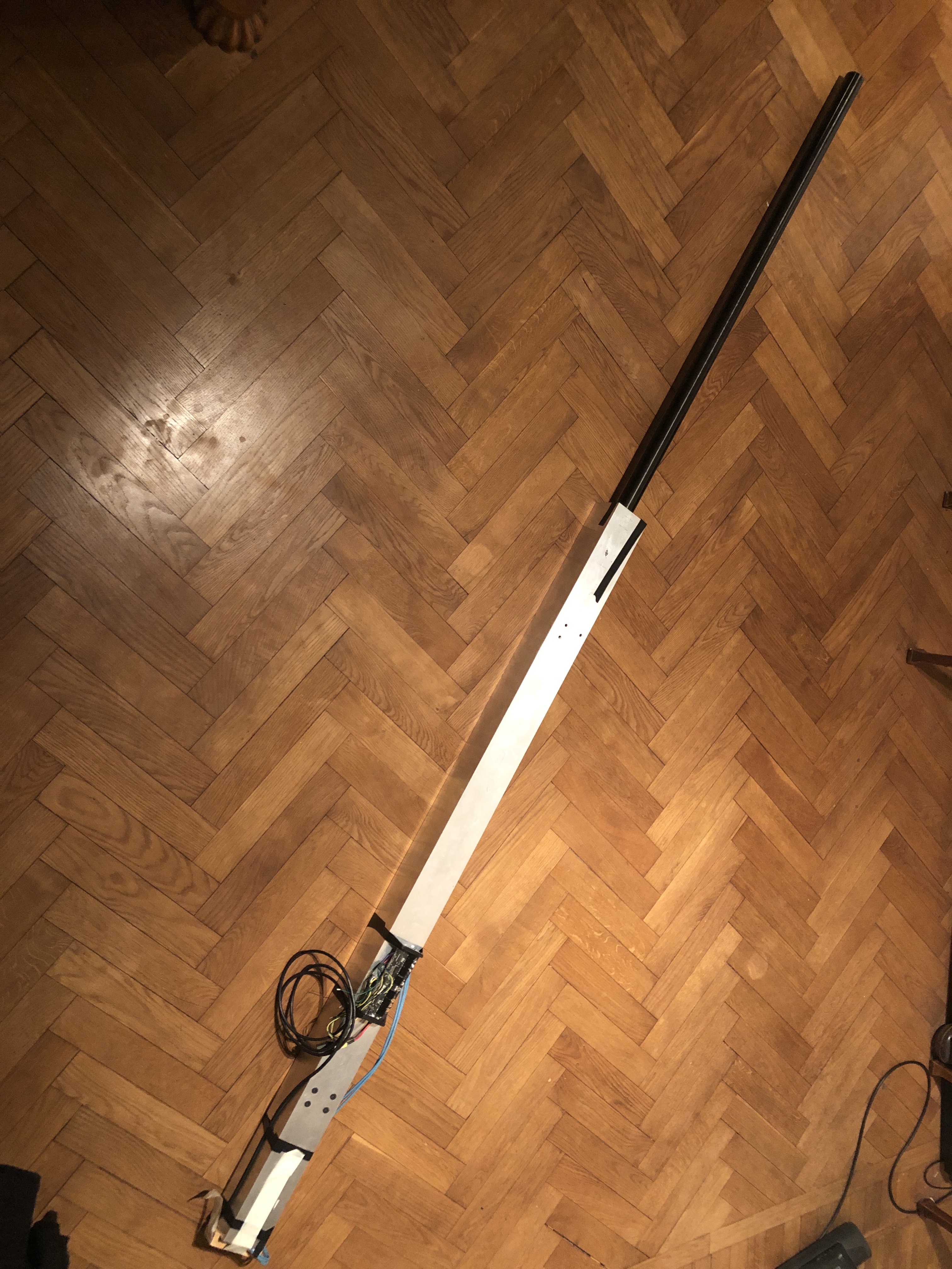
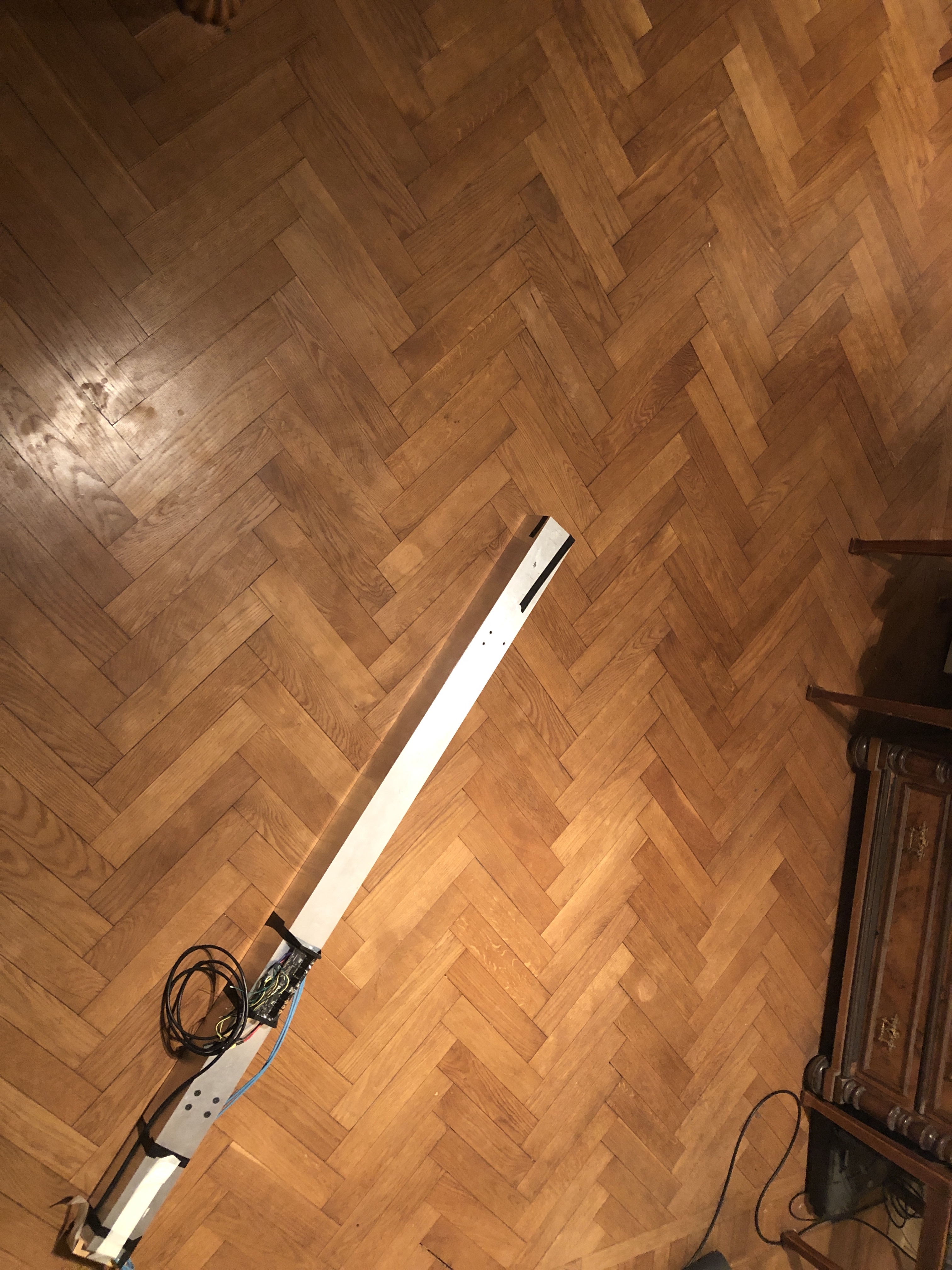
I thought that maybe I should share my build of linear actuator, which is planned to be part of a hexapod. It has a 1050mm stroke and is 1500mm long retracted, but I think I can cut it down to 1400mm at least. It should have a max speed of at least 600mm/s (maybe will get it up to 800mm/s) and be able to lift about 100kg.
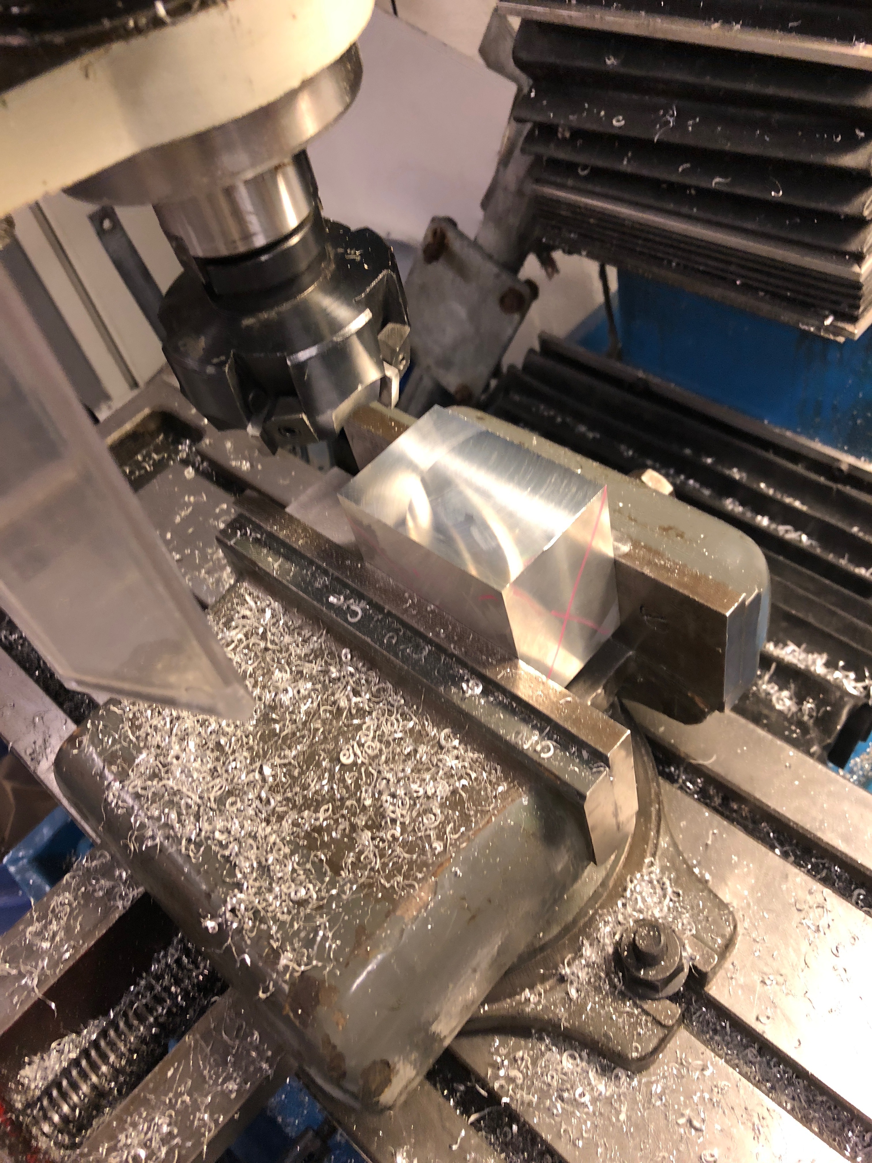
My goal is to use as few custom machined parts as possible and be able to use industry standard parts to the greatest extent. An other design goal was to make it easy to machine the parts in a way that the errors/backlash of the mill affect the tolerances/alignment in a minimal way.
The parts I’ve used this far:
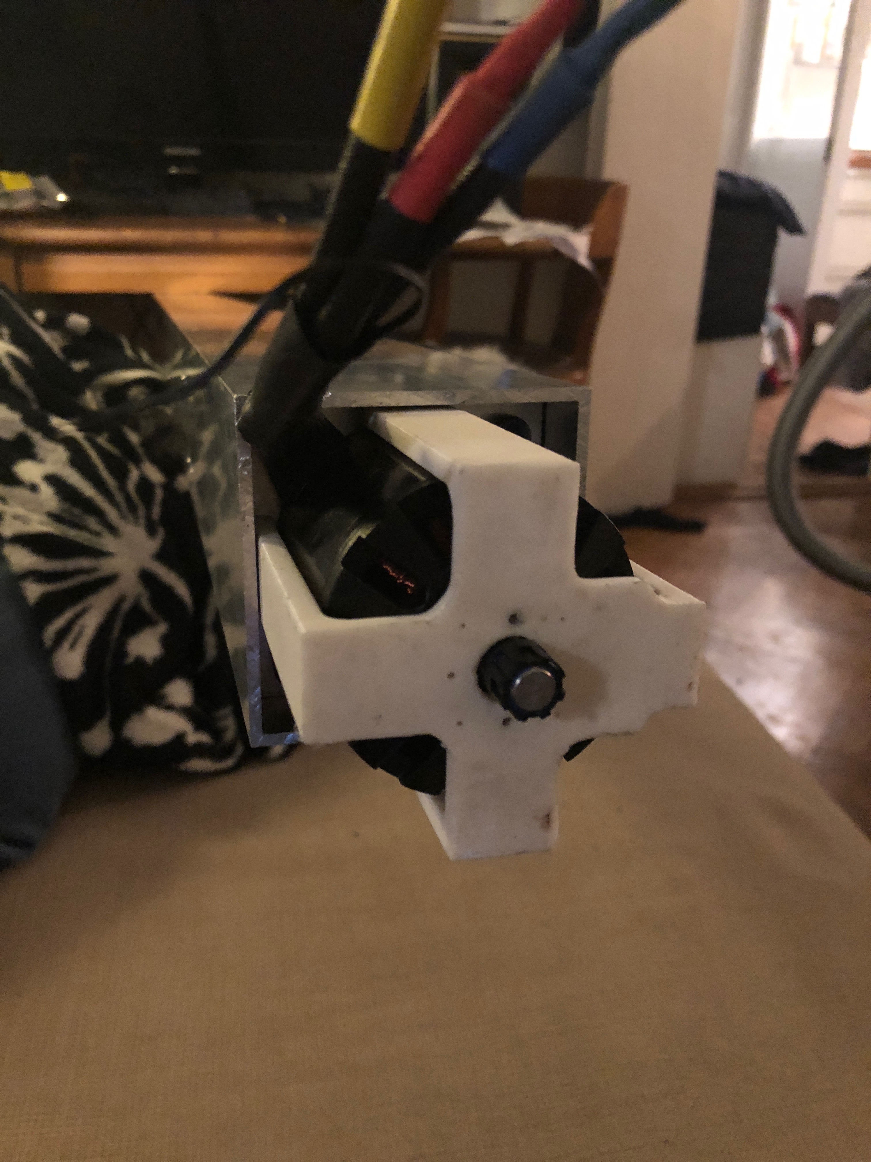
Odrive 48v
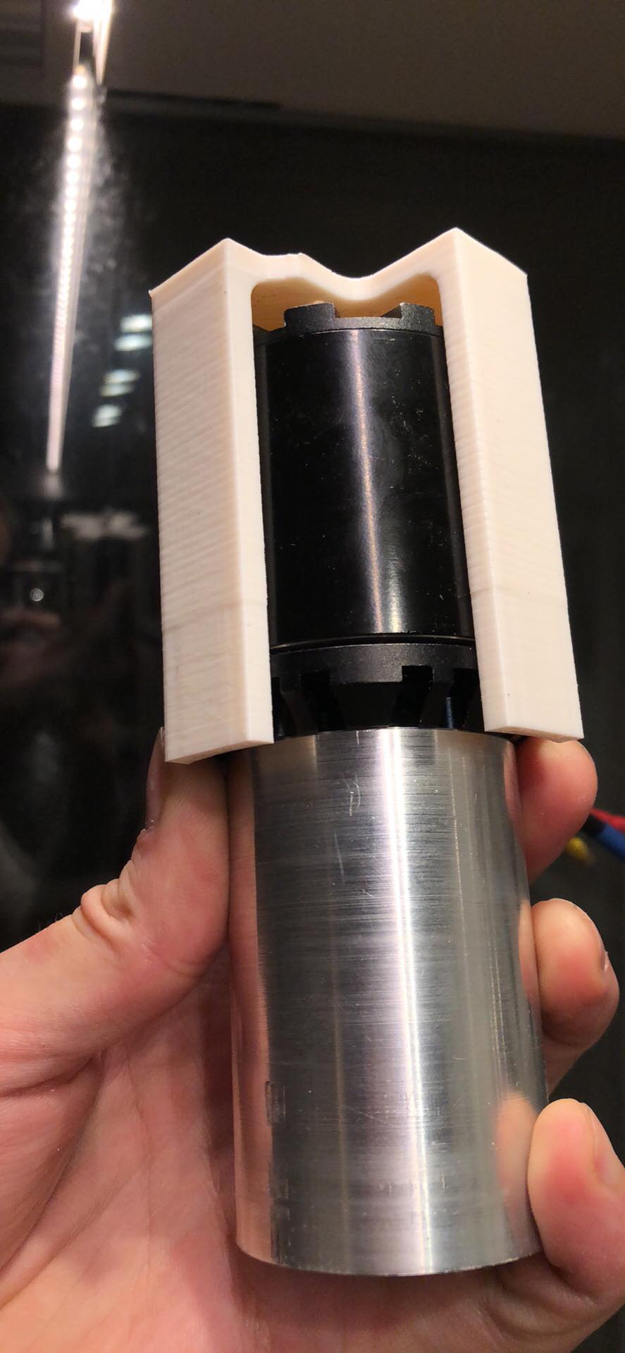
Odrive dual shaft motor D6374 150kv
CUI 8192 CPR encoder
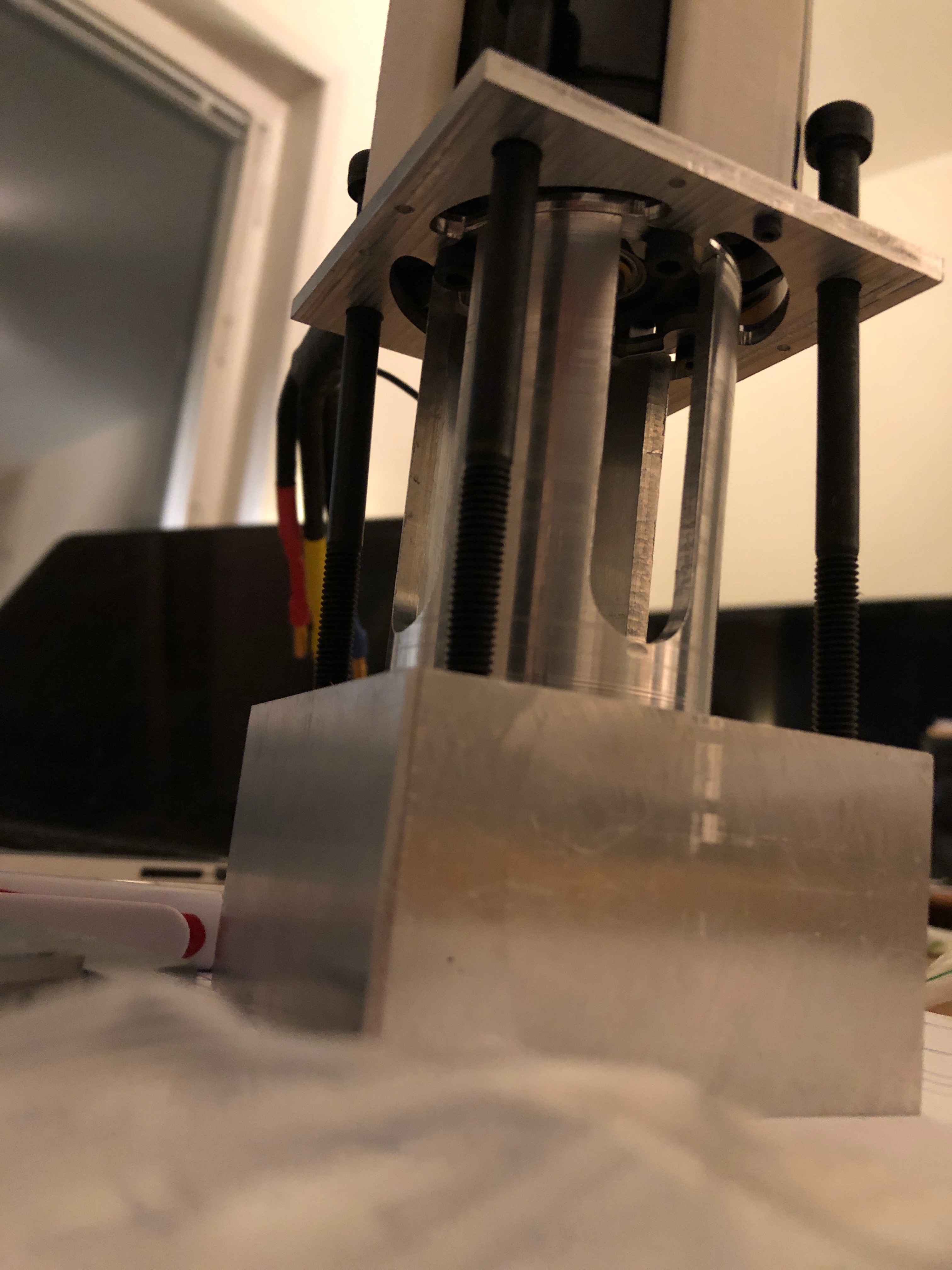
Square aluminium tube 80x80x3x1500mm
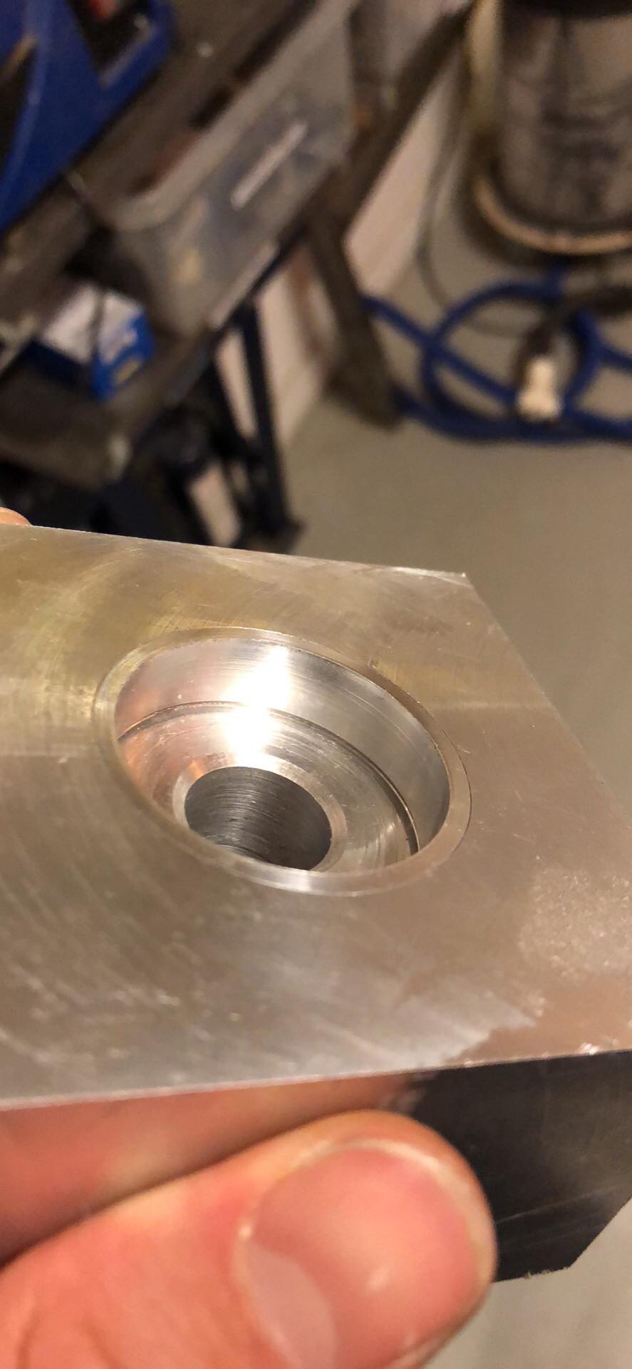
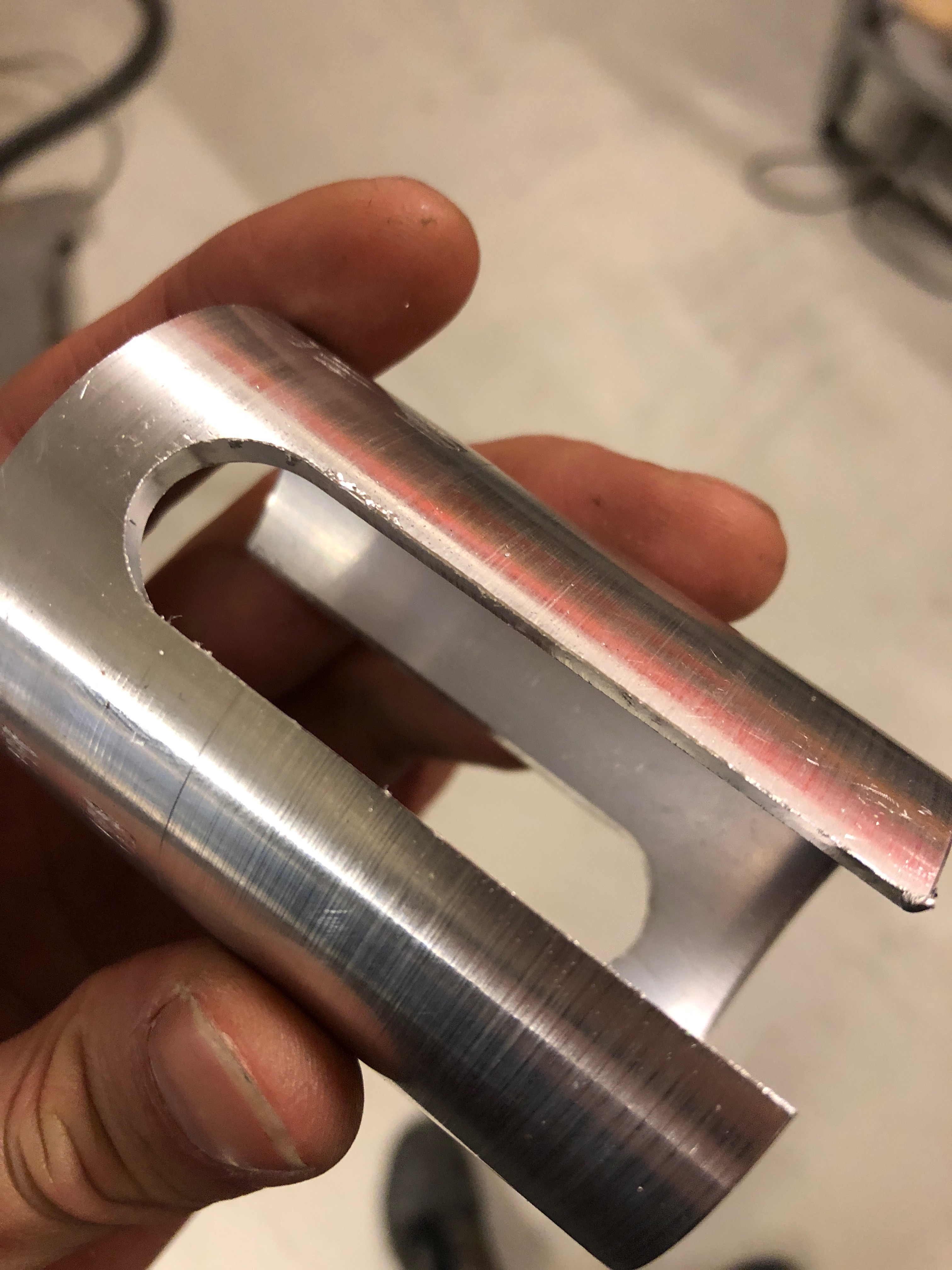
SFU2010 1200mm ballscrew with custom end machining
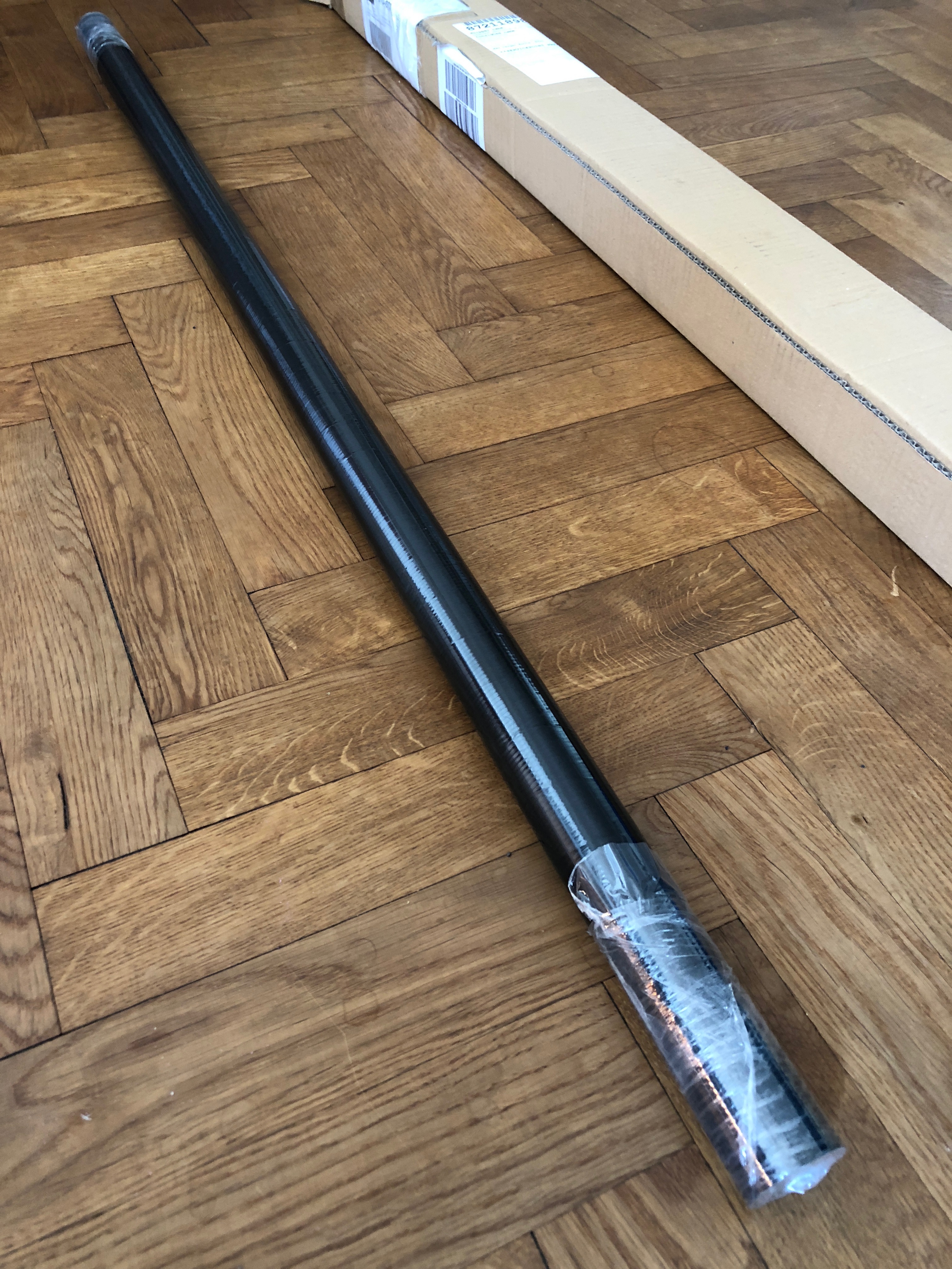
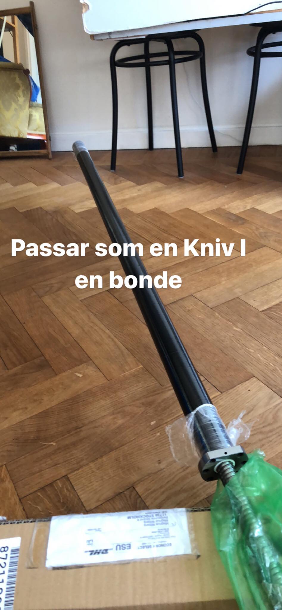
Carbon fibre tube 36mm ID 40mm OD 1200mm
Aluminium tube 40mm ID 48mm OD 80mm (used for distance/alignment)
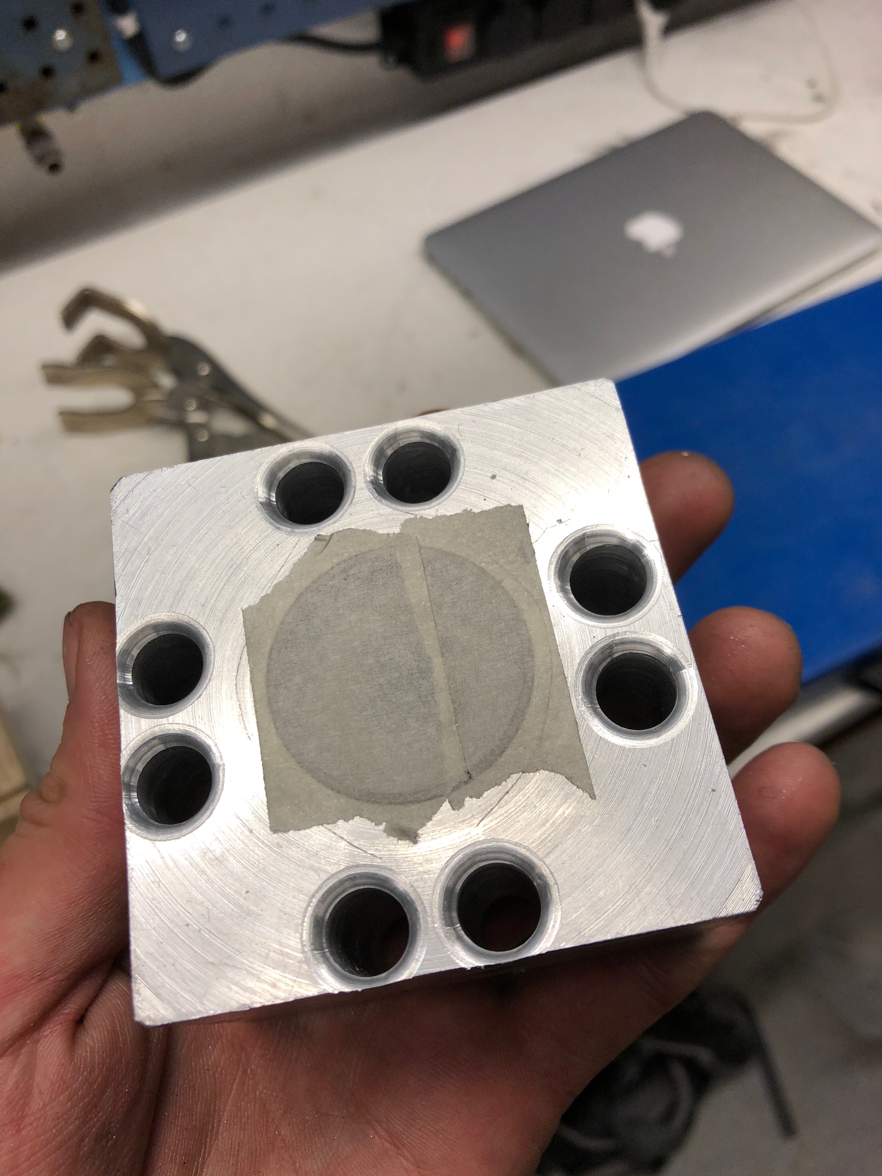
2 Conical roller bearings
2 Skateboard bearings
Rigid 10mm coupling
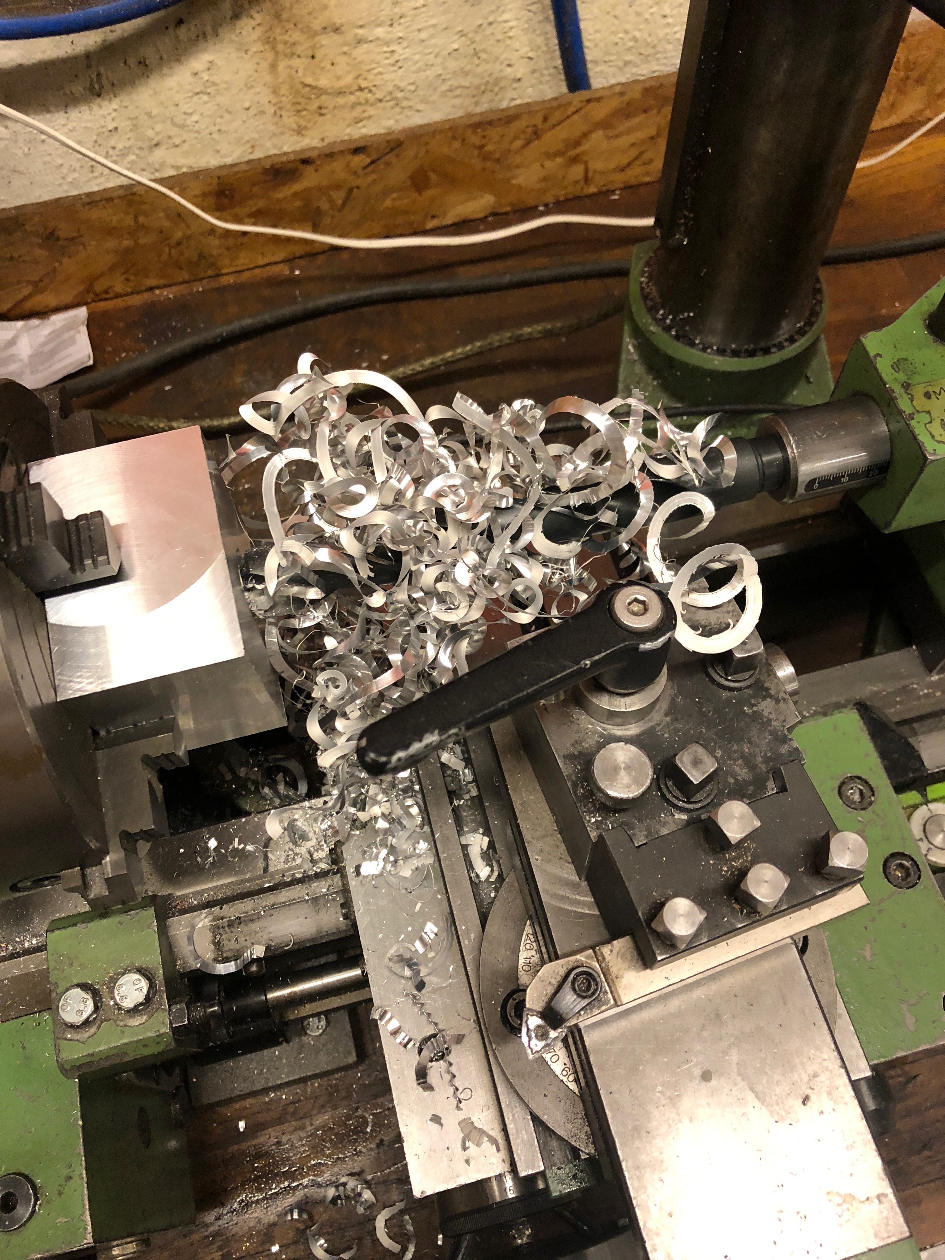
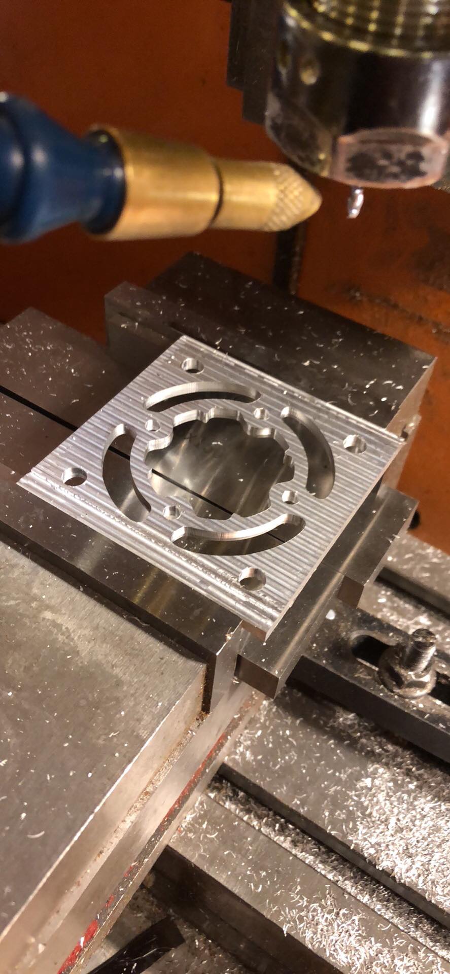
A couple of slabs of aluminium to machine.
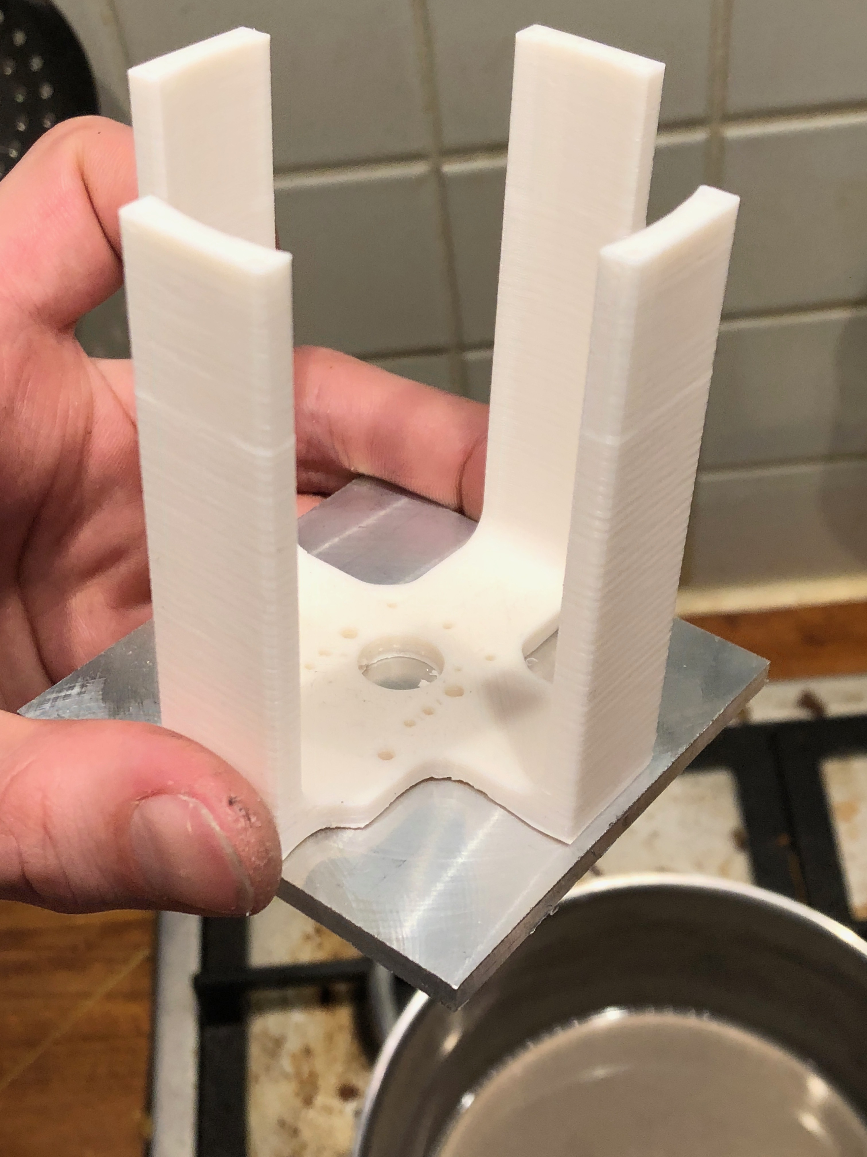
Filament for 3d printed parts (such as temporary bruchings, encoder mount, temporary ballscrew nut carrier)
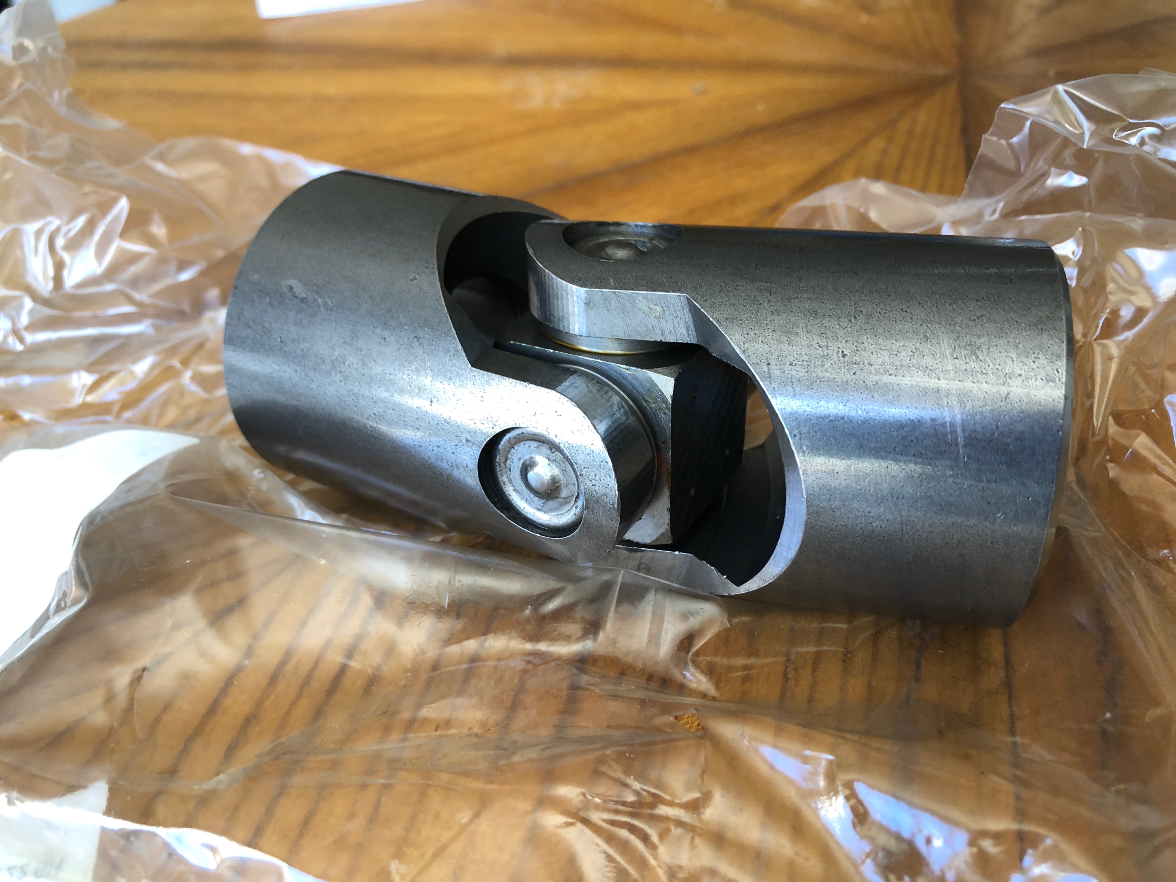
A huge universal joint
An assortment of screws
(planned 60mm server fan for cooling)
(For control I’m planning to use step/dir output from a Beagleboard X15 with machinekit. It needs a bit more tinkering. If someone wanna help out/do a joint project to make this x15 as wonderful of a controller as I know it could be please contact me )
(Also a future plan is to build an interferometer to calibrate for imperfections of the ball-screw pitch and measure precision. )
It is a 10mm pitch ball screw. Max rpm of the motor, according to the odrive motor guide, is 5760 rpm. This should give me 5760rpm/(60s/min)*10mm/rev=960mm/s. What I get is 500000 counts/s which is 500000 counts/s /(8192 counts/rev) *60 s/min = 3662 rpm. Or 500000 counts/s /(8192 counts/rev) *10mm/rev=610mm/s. I get about 64% of the speed performance I would expect.
In the thread I linked there is more information of the max speed issue and I have a post there specifying the maximum speed reached and with what settings/parameters.
I was able to lift myself with it ~85kg. I would like to plot the current while doing it though since it didn’t go with as high velocity as I would have liked. The power required to lift me with continuous velocity with 90% efficiency should be 0.9x3000w / (85kgx9.82m/s^2)=3.23m/s, well below the actuator max speed. Or the power needed for 0.9m/s constant velocity should be 0.9m/sx85kgx9.82m/s^2 /0.9 = 835w.
If I assume 100kg is the max force it can exert, that is 982N. My weight is 835N. That leaves 982-835=147N. That force should accelerate me 147N /85kg=1.7m/s^2. I should accelerate to max speed in less than a second, and I did NOT feel that acceleration.
(If you se any errors in my calculations please point them out )
Yes they are indeed very similar designs. My main objective was to reduce the number of custom parts as much as possible which resulted in this design, but I think I can reduce the number of custom parts even more with some small changes in the design. I have yet to build the carrier guiding the ball screw nut in the square tube and counteract the rotation of the ballscrew nut around the ball screw. From what I can see from your design you’re using linear bearings to counteract the rotation of the ball screw nut?
No, this is not correct, the guide is to take out there side load on the ball nut because this is the weakest point in the system. Because you are using universal joints, you need to allow rotation inside the actuator, I’ve done this by letting the guide block rotate around the ball nut
Ok I see. I want to lock the rotation of the ball screw nut or I will get some coupling between rotation and position. This is ok for simulators, but would reduce the precision which would not be good for my second application of the hexapod: CNC. I will mount the universal joint to the platform/base with a bearing to allow for rotation.
As for side loads, what loads do you mean? The actuator will only take up axial forces if mounted with universal joints in both ends. Are you planning to mount it some other way? Sure the buckling failure mode will result in in a side loads, but my calculation says that the point of buckling is 100kg for a 1100mm 13mm diameter rod. The sfu2010 ballscrew have a minor diameter of 17mm, so buckling should not be an issue at static load.
When running with at higher speed there might be some whipping, but I planned to test first to see if this is a real issue. The equations I used to calculate when whipping occurred gave me a rpm of around 5000rpm with a 1100mm unsupported length of ball screw. If whipping becomes a problem my plan is to build a “floating” support. But a solution like your linear bearing might be an easier solution. If you would like to share your calculations I would be happy to see them .
 )
)


 )
)