I get the motor error ERROR_BRAKE_CURRENT_OUT_OF_RANGE when pushing a BLDC to high speeds.
What are the conditions that trigger this error? Is it something that can be adjusted?
Thanks.
1 Like
When this error happens, Iq_measured is greater than current_lim, I’m guessing thats why the error is triggered.
Iq_measured is also well over 10 times greater than Iq_setpoint, is that normal?
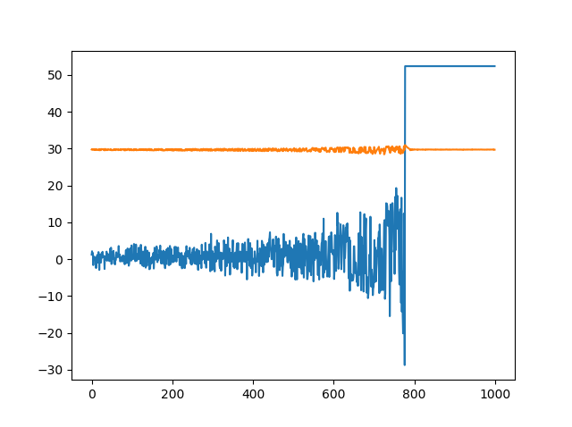
The graph shows Iq_measured (in blue) and vbus_voltage (in orange) as the speed is increased until it trips with the error Brake Current Out of Range. Current Limit set to 70A in this instance and Iq_measured trips at just over 50A. Is the ripple on vbus_voltage significant? I’m measuring about 2v pk-pk on vbus at the point of error.
This looks like the current controller is not quite stable at this combination of motor, speed and bandwidth.
Can you dump your odrv0.axis0.motor.config? What speed were you running at when it craps out?
In [6]: odrv0.axis0.motor.config
Out[6]:
pre_calibrated = False (bool)
pole_pairs = 7 (int)
calibration_current = 10.0 (float)
resistance_calib_max_voltage = 1.0 (float)
phase_inductance = 5.0343669499852695e-06 (float)
phase_resistance = 0.021794622763991356 (float)
direction = -1 (int)
motor_type = 0 (int)
current_lim = 70.0 (float)
requested_current_range = 90.0 (float)
current_control_bandwidth = 1000.0 (float)
The odrv0.axis0.controller.set_vel_setpoint is just over 170000 (about 5000 rpm) when it errors.
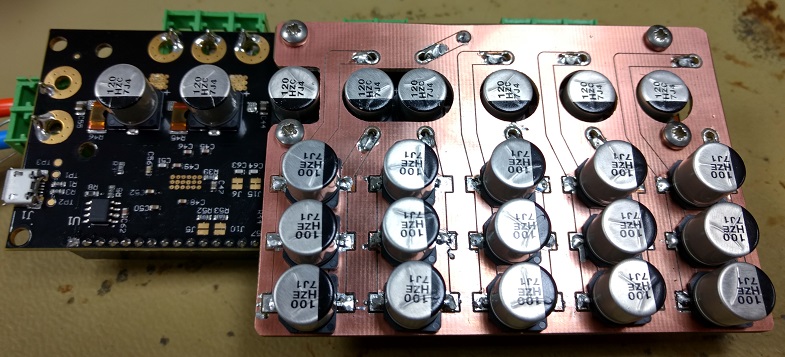
This is the motor
I’m going to order some more capacitors to parallel across the bulk capacitors on board to see if that helps.
What encoder are you using? I will be getting the same motor here in a few days: do you happen to have some 3D printable or lasercuttable test stand? That would help me reproduce your issue faster.
The encoder we’ve been using is a HEDS-9140#A00 with HEDS-5140#A12 codewheel, we’ve also tried fitting 3 Hall sensors, honeywell ss41 and also running sensorless. All three methods result in the same error, Brake Current Out of Range, although the Hall sensors produce the error at a much lower rpm. Sensorless errors about the same rpm as using the encoder wheel.
I’ve also had slightly different maximum rpm from 3 different power supplies, albiet with a previous version of hardware. There is a post from Texas Instruments about the DRV8301 where someone asks for a guide on bulk capacitance, to which their reply is rather vague, which is hinting to me that maybe the capacitance needs beefing up, so I’ve ordered 15 of these capacitors to add to the ones on board.
And this is with basically just the motor spinning, no significant external load mass or drag?
What is the settings you use for controller.config (for both encoder fb case, and sensorless), and what about encoder.config when using the HEDS encoder?
I suppose more bus caps could help stabilize the current controller, but it shouldn’t be necessary. I will investigate the instability issue when I have time to set up the test rig with the 580kv Propdrive motor.
We are generally running the motor at this test stage unloaded, but have applied a light load to see if that makes any difference, there was no significant difference.
The controller config we use for the HEDS encoder is:
control_mode = 2 (int)
pos_gain = 1.0 (float)
vel_gain = 0.0010000000474974513 (float)
vel_integrator_gain = 0.0010000000474974513 (float)
vel_limit = 400000.0 (float)
The controller config we use for sensorless is:
control_mode = 2 (int)
pos_gain = 20.0 (float)
vel_gain = 0.009999999776482582 (float)
vel_integrator_gain = 0.05000000074505806 (float)
vel_limit = 400000.0 (float)
The encoder config we use for the HEDS encoder is:
mode = 0 (int)
use_index = False (bool)
pre_calibrated = True (bool)
idx_search_speed = 10.0 (float)
cpr = 2000 (int)
offset = 1021 (int)
offset_float = 1.2579481601715088 (float)
bandwidth = 1000.0 (float)
calib_range = 0.019999999552965164 (float)
Thanks Oskar
Tried fitting extra bulk caps, no luck. It even had the effect of LOWERING the rpm at which the error occurs by about 400 rpm.
I tried the motor, and I was able to spot the cause of the issue on my oscilloscope current probe: the ripple current is way too large. The combination of ODrive’s low default switching frequency and the low inductance of the propdrive motor gives excessive ripple current.
The duty cycle of an unloaded motor is given by:
d = \frac{RPM/K_V}{\frac{2}{3}V_{bus}}
Your issue was the worst at around 5000 RPM, which for a 580 Kv motor gives a duty cycle of about 40% when on a 30V supply.
Here is the theoretical ripple current as a function of duty cycle for your motor:
A_{ripple} = \frac{\frac{2}{3}V_{bus}}{L_{phase}\;f_{sw}} \; d \; (1-d)
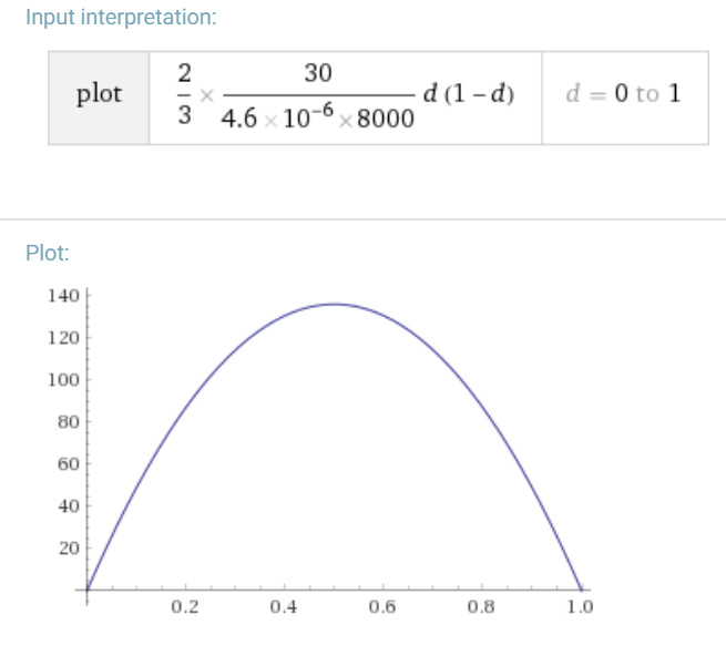
At 40% duty you would be getting a ripple current of almost 140A. This explains why the bus voltage was starting to ripple. Also the current controller would be getting issues because the current sensors were saturating. I’ll make a note to add an explicit fault for current sensor saturation so nothing gets destroyed in a situation like this, and so error messages are more helpful.
The way to fix this is simply to use a higher switching frequency. The hardware is designed to switch at 24kHz, but we are currently switching at 8kHz. The reason is that the trigger for the execution of the control loop is tied directly to the switching frequency, and we don’t have the CPU to run the controller that fast. The obvious solution is to decouple the control loop execution to only run every Nth switching cycle. This is a bit of work to do, and we haven’t had a reason to until now.
I’ll make a feature request on github as soon as their servers are back to working again.
1 Like
Great work Oskar. Thank you.
We now have 24kHz switching frequency with 8kHz control frequency on devel!
@Neil_FV please go ahead and try it, it should reduce the ripple current by factor 3.
I was mistaken on how difficult decoupling the control rate from the PWM frequency was, it turns out it was quite straightforward. There was one complication to do with timestamping the control performance, but I was able to deal with that. Also thanks @Wetmelon for your help with this.
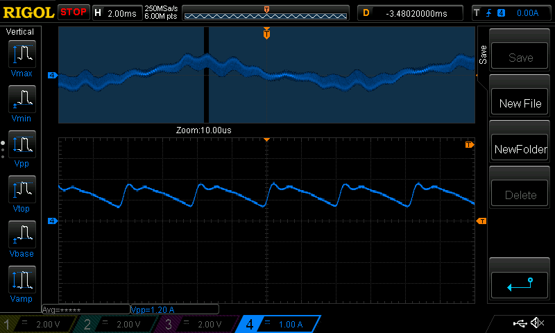
I tried it on the same low inductance motor: the Propdrive 5050 580kv. The ripple current goes from about 4.2A pk-pk to about 1.2A pk-pk. Note that the current clamp has a ~5us time constant low pass filter, the real waveform would be sharp sawtooths.
Before:
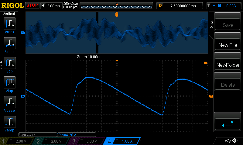
After:
1 Like
Great work @madcowswe and @Wetmelon, I can confirm the ripple is reduced to about a third, though the motor still errors at the same speed with the same error.
Interesting. I’ll try spooling it up to a higher speed here when I get the time.
Do you have a script to ramp up the speed, or how do you ramp the speed up in a controlled way for testing? That would be useful for my testing on this end.
I’ve been using this script to facilitate testing, I’ve only been using axis0, so its only really set up for that.
Thanks
Hi,
Sorry not just yet. I have the test rig all set up, and it’s at the top of my todo list. Hopefully in a day or two.