Swiss type Mill Turn center

Hi Oscar and everyone!

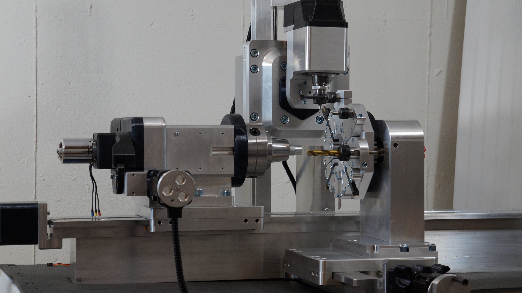
I’ve been stalking you all since early 2016. Prior to that I thought I would have to make my own closed loop BLDC controller, but then I found ODrive, so I scrapped what I had on the electrical side and focused on the mechanical stuff. Long story short, this project is the version 2 prototype swiss mill turn center.

If you’re unfamiliar with the concept, just youtube some videos of swiss cnc lathes and mill turn centers.

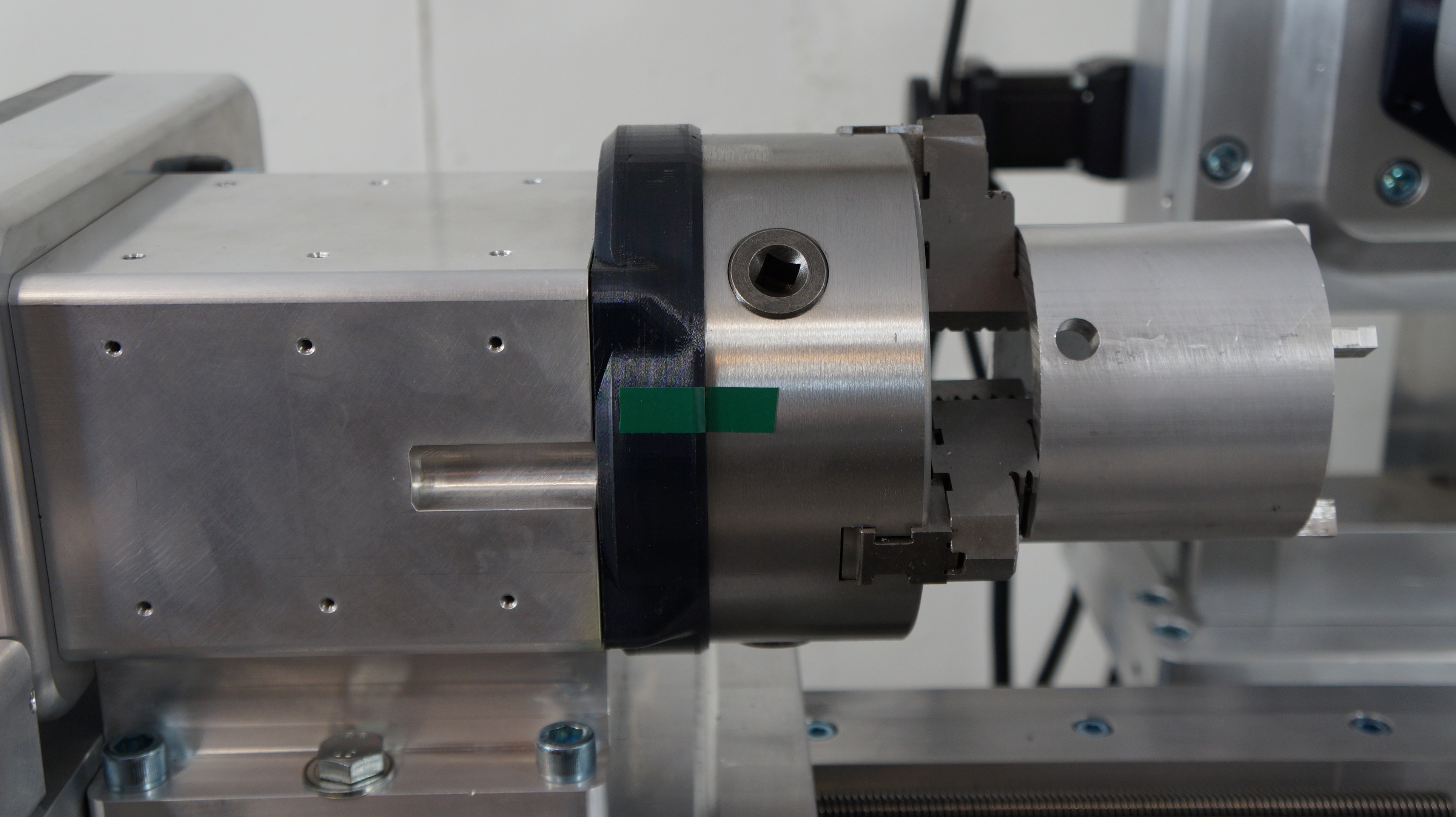
The reason I’m posting now is because I’ll be launching a kickstarter for this machine fairly soon, but I don’t yet have all the information I need about the ODrive and what I can expect. Right now the machine uses dual shaft steppers, with the spindles being powered by 63mm outrunners. I planned on integrating this machine with the ODrive controller from the beginning, so the motor shafts are 8mm to fit the CUI AMT series encoders.

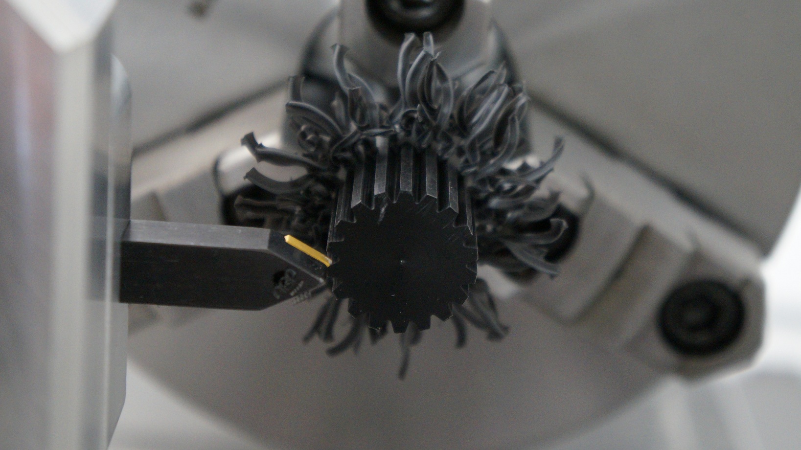
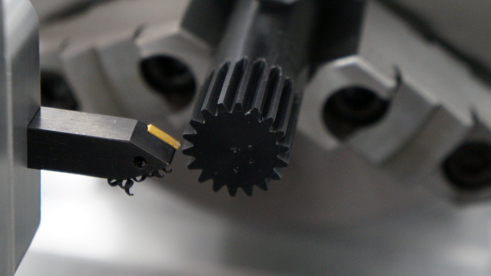
The ultimate goal is to have the machine capable of running O-Driven motors on all axes, especially the spindles, which will give it the same capability as the full sized industrial machines. Rigid tapping, spindle orientation, and synchronized skiving / hobbing (for gears) are attainable with the ODrive. The positioning axes would also benefit from slightly improved resolution, but speed and linear thrust would be greatly increased. Steppers can’t rotate the B axis mill head and C axis workpiece fast enough for most simultaneous 5 axis machining operations.

Sadly my machine doesn’t have an O Drive right now. I was a couple clicks away from buying one in late November, but then v3.3 sold out and I couldn’t wait until the end of December. Also there is no bootloader yet (I think?) and I didn’t want to gamble on my ability to flash firmware with 3rd party linux software.

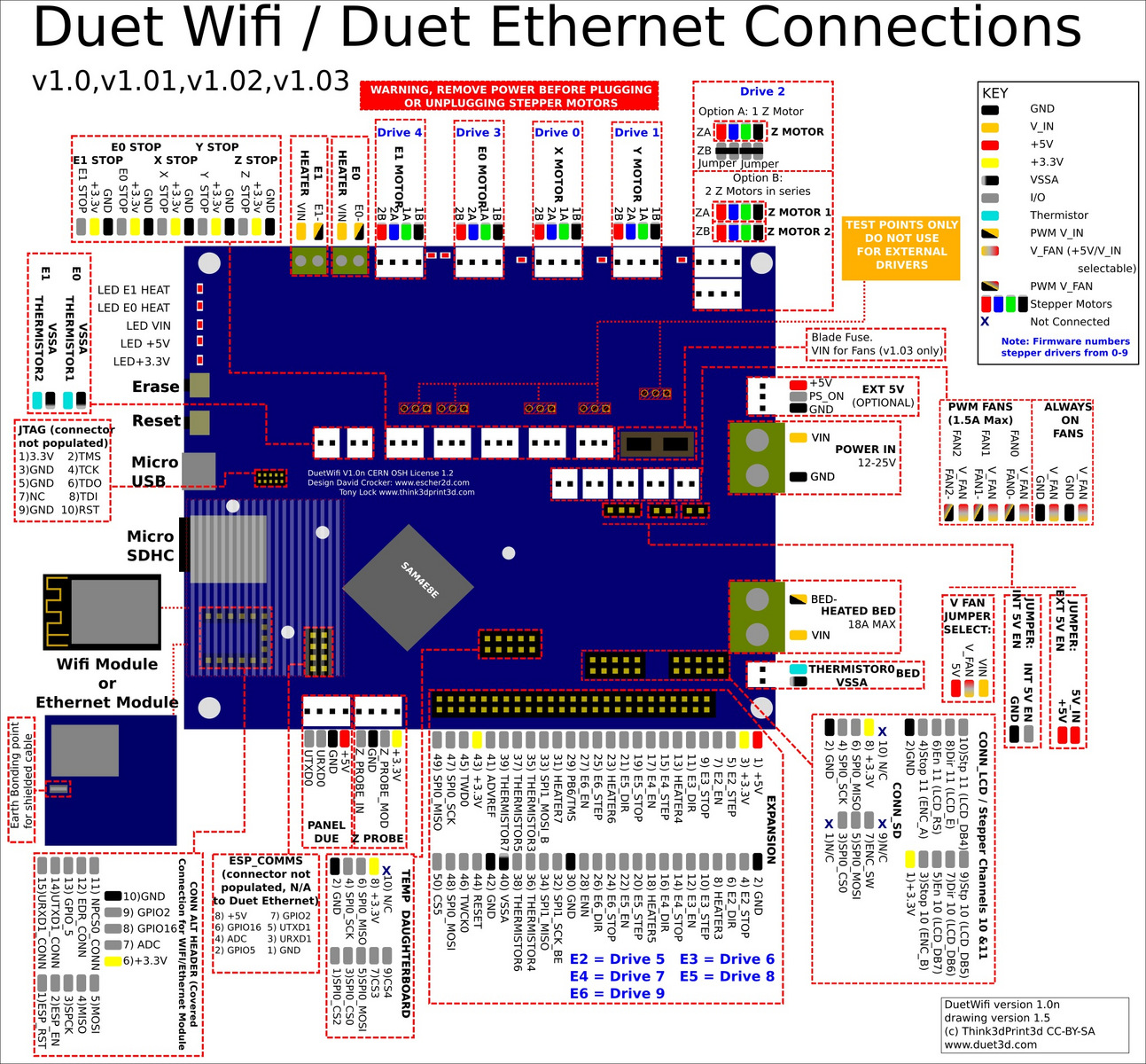
The plan is to use 1 or more O Drive controller[s] (48v) that take commands from some type of 3d printer controller (smoothieboard, azteeg, duet, ect) and send data back that can be displayed on a touch screen. Right now I have to use a VESC to control the spindle motors because ODrive doesn’t have the communications and the IO stuff isn’t quite where I need it to be. But I know it will get there soon enough, so it’s my top choice.

I can only upload one picture since I’m new on this forum, I’ll get a bunch more in subsequent posts.
Can’t wait to get it working with an ODrive!

Check out this forum thread for more pictures;

http://forum.seemecnc.com/viewtopic.php?f=41&p=107454&sid=275fde61fc97b559758bc7809c3109c6#p107454

12 Likes

That looks frickin amazing!
Please keep us updated on the Kickstarter and good luck

1 Like

Wow this machine looks super awesome! From the point of view of me personally, I want this machine; I think if you can make some cool demos, your kickstarter will go well, other people will want it too.

Also from the point of view of the ODrive project, this kind of machine would be a very good fit. There has been a lot of interest for using ODrive with machine tools, but this is really next level. I think this is really exciting and I want to help make this happen. I would be happy to spend extra time supporting this project, since I think the outcome would be a very good showcase of the ODrive too.

To get the collaboration rolling, I’d be happy to send you a free 48V ODrive. I would also be happy to do a call to discuss what your needs are, and to go through the current capabilities of ODrive and what the roadmap and timelines are. Feel free to email me at oskar.weigl@odriverobotics.com to schedule it, if you are interested.

ODrive already supports step/dir input, and can output various feedback over either UART or USB. But there may be other options too, so I want to know what the requirements you have for the interface to your machine?

4 Likes

Hi GenericDefault, this looks amazing, and I wish I had this 20 years ago when I was Making gold and platinum watches by hand.
Man that would have make a huge difference; I would have spent 150 hours on a custom design, this would have saved me a great deal of time!

I wish you all the best in this project.

Regards Jerry.

1 Like

Still filming the kickstarter video, here’s a demo part I made a few hours ago;


Parts like this are single point broached; the tool tip shears off a little bit of material by moving along the side of the part. It’s one of the more time consuming operations since the spindle motor does no work. This one was done with steppers, it took just over 8 minutes to cut 18 spur teeth.

This is the type of part that would benefit greatly from a fast Odrive servo. Having more torque means the machine axis that is doing the work (cutting) can take heavier, deeper cuts. With a servo, it could also cut much faster. I’m guestimating that with an Odrive on the X turret and Z headstock axes, this spur gear could have been done in under 2 minutes rather than 8.

One of the clips I want to get in the video is a comparison of a machine axis moving with steppers vs ODrive servos so you can see for yourself!

5 Likes

Wow, this is just AWESOME!
Shut up and take my money NOW!

3 Likes

odrivegif2
This is a half-sized GIF from the Odrive segment of the kickstarter video. Had to keep it under 3MB for this forum.


Just a quick update. This was the first power-up test of the Odrive on this machine.

It’s coupled to the spindle at a 1:1 ratio with a big herringbone pulley. The 6 inch chuck and big bore spindle have quite a large moment of inertia, over 500 kg*cm^2. The motor is a SK3 6374 at 149kv. I can turn the motor case by hand easily, it seems like the torque limit is very low in the firmware. It still homes to within a few degrees though. I don’t think the encoder is ideally seated, it may have a small amount of play in it.

Once the firmware PID stuff is set and tuned correctly, I’m hoping to get a snappy, ultra-precise home sequence that immediately rotates to a set position and holds rigidly.

Oskar, what settings should I change in the firmware to account for a huge inertial load with no gear-down?

2 Likes

Awesome! Can’t wait to see it tuned!

Before tuning too aggressive, I would make sure there is no play in the encoder: that can give intermittent instability which can be a big pain to deal with.

The tuning procedure is documented here. Though because you have quite a safe system (can’t smash into endstops), you can bump the current_lim to 70A straight away, so you can do the tuning on a more realistic max torque. Also because you have an estimate of the mechanical inertia, we can cut some corners and use theoretical calculations to get a good starting point for vel_gain.
The calculations show that a value of .vel_gain = 1000.0f / 10000.0f, // [A/(counts/s)] should be suitable, though I would start by setting it to 1/10 of that (100/10000) and increase it from there, testing stability in every iteration.

If you want the positioning to be repeatable between power cycling the ODrive, you need to enable the index pulse feature, which you can do by following these instructions.

2 Likes

I can’t reach the USB or STlink from my desktop to the Odrive while it’s plugged in, so I have to unplug all the wires to the Odrive, move it near my PC, then plug in all the programming wires from the STlink.
The first time I did this to change the parameters like you suggested, it looked like it worked. So I unplugged it from my PC and reconnected it to the machine stuff.

But it didn’t work, the system gave the same sluggish behavior as if it was running with the original 10 amp limit, and now when I try to build the firmware it just gives a missing path error.

I would suggest using a laptop or a long usb cable, because tuning is quite an iterative process.

So in the screenshot you provided, actually it finished building, because it says “Nothing to be done for ‘all’”, which means that it has nothing to do because nothing was changed since last successful compilation. I don’t know what the file is that it couldn’t find, but yeah the compilation is OK.
The next step is to actually move the code to the ODrive, which is with either the command make flash in Bash, or with Tasks -> Run Task -> flash in VSCode.

If you want, I’d be happy to provide realtime support over on the discord.

Thanks for helping me on the Discord channel Oskar, I think I got the hang of changing, building, and flashing the firmware now.

Here’s a video of the first 3 tests, the third one is probably closing in on the best tracking performance given the less than ideal mechanical setup. I think the Odrive will be more suitable for direct-driving the milling spindle rather than the turning spindle, since the milling spindle has a fraction of the rotary inertia (~10 for the milling spindle compared to ~600 for the turning spindle).

Of course, this is a reasonably large workpiece held in a 6 inch steel chuck all driven by a shaft that’s about 6mm in diameter at it’s narrowest point. It still looks good enough to thread a small workpiece in this state. The milling spindle will probably handle rigid tapping just fine.

1 Like

This project looks amazing. I have never seen this kind of machine before but what a wonderful example of the genre. Do you use a tailstock with it much and what kind of holding torque do you want on the turning spindle?

There’s no tailstock on it right now, but there is a boxway slab on the right side of the machine that’s intended for a tailstock, subspindle, or just to hold vises like a regular 3 axis mill.

The turning spindle actually has a worm gear that can be engaged for high torque operations. The motor you see in this video is the main turning spindle, which has to be able to spin the whole thing to at least 2000 RPM (the limit of the chuck).

In the servo test video above, I’m just evaluating the direct drive for indexing use. The production version of the machine will be greatly improved.

I was just looking at the Duet board wiring map again.
It looks like the CONN_LCD port in the lower right corner of the board would be perfect for plugging the first ODrive board into on the production machine. That leaves 5 regular stepper drivers open and unused for the linear axes of the machine, since each machine will need at least 1 ODrive board for the main turning spindle and/or milling spindle. I want to have the STEP/DIR pins on the ODrive plugged in so they can be controlled like regular stepper axes without using any digital communication protocols.

Someone needs to create a board that has a bunch of convenient step/dir outputs but no stepper drivers, that runs the same firmware as whatever is popular. So what’s popular?

There is a big collection of open source motion controllers that run Marlin on a slow and crappy controller which have you plug in polulu step sticks. One example is the Ramps board.

There is also the JuicyBoard which is doing a modular concept version of the Smoothieboard.

@Wetmelon
This seems like a good choice: http://www.panucatt.com/azteeg_X5_mini_reprap_3d_printer_controller_p/ax5mini.htm

It runs smoothieware, it’s cheaper than the JuicyBoard, it has mosfets built in, and it uses 0.1" headers instead of the annoying connectors on the JuicyBoard.

Not sure if Cohesion3d has been mentioned but worth including in a consideration of smoothieware compatible boards (http://cohesion3d.com/motion-controllers/)

1 Like

I think both of those boards are suitable for some variants of the machine. The azteeg x5 has 4 stepper ports, which would be good for a 3 axis machine and a spindle. Rather than put the stepper drivers into the ports, you could just plug the step and dir pins of two Odrives into the stepper outputs on the board.

The cohesion with 6 stepper ports would be useful for one of the lathe variants or the mill-turn variant as long as there was some way to get one more motor output for the turning spindle, or if it was to be used without the turning spindle. The Duet board with up to 12 motor outputs would be for the most complex variants with the most axes.

@GenericDefault

too bad you didn’t mention this project earlier.

I commited 5k€ on a proxxon lathe just a few days before your message on the forum :cry: :cry: :cry:

good luck with kickstarter